
The Raspberry Pi is fast enough to be used to directly interface to 1-Wire bus without the need for drivers. The advantages of programming our own 1-wire bus protocol is that it doesn't depend on the uncertainties of a Linux driver.
Now On Sale!
You can now buy a print or ebook edition of Raspberry Pi IoT in C from Amazon.
For Errata and Listings Visit: IO Press
This our ebook on using the Raspberry Pi to implement IoT devices using the C programming language. The full contents can be seen below. Notice this is a first draft and a work in progress.
Chapter List
-
Introducing Pi (paper book only)
-
Getting Started With NetBeans In this chapter we look at why C is a good language to work in when you are creating programs for the IoT and how to get started using NetBeans. Of course this is where Hello C World makes an appearance.
-
First Steps With The GPIO
The bcm2835C library is the easiest way to get in touch with the Pi's GPIO lines. In this chapter we take a look at the basic operations involved in using the GPIO lines with an emphasis on output. How fast can you change a GPIO line, how do you generate pulses of a given duration and how can you change multiple lines in sync with each other? -
GPIO The SYSFS Way
There is a Linux-based approach to working with GPIO lines and serial buses that is worth knowing about because it provides an alternative to using the bcm2835 library. Sometimes you need this because you are working in a language for which direct access to memory isn't available. It is also the only way to make interrupts available in a C program. -
Input and Interrupts
There is no doubt that input is more difficult than output. When you need to drive a line high or low you are in command of when it happens but input is in the hands of the outside world. If your program isn't ready to read the input or if it reads it at the wrong time then things just don't work. What is worse is that you have no idea what your program was doing relative to the event you are trying to capture - welcome to the world of input. -
Memory Mapped I/O
The bcm2835 library uses direct memory access to the GPIO and other peripherals. In this chapter we look at how this works. You don't need to know this but if you need to modify the library or access features that the library doesn't expose this is the way to go. -
Near Realtime Linux
You can write real time programs using standard Linux as long as you know how to control scheduling. In fact it turns out to be relatively easy and it enables the Raspberry Pi to do things you might not think it capable of. There are also some surprising differences between the one and quad core Pis that make you think again about real time Linux programming. -
PWM
One way around the problem of getting a fast response from a microcontroller is to move the problem away from the processor. In the case of the Pi's processor there are some builtin devices that can use GPIO lines to implement protocols without the CPU being involved. In this chapter we take a close look at pulse width modulation PWM including, sound, driving LEDs and servos. -
I2C Temperature Measurement
The I2C bus is one of the most useful ways of connecting moderately sophisticated sensors and peripherals to the any processor. The only problem is that it can seem like a nightmare confusion of hardware, low level interaction and high level software. There are few general introductions to the subject because at first sight every I2C device is different, but here we present one. -
A Custom Protocol - The DHT11/22
In this chapter we make use of all of the ideas introduced in earlier chapters to create a raw interface with the low cost DHT11/22 temperature and humidity sensor. It is an exercise in implementing a custom protocol directly in C. -
One Wire Bus Basics
The Raspberry Pi is fast enough to be used to directly interface to 1-Wire bus without the need for drivers. The advantages of programming our own 1-wire bus protocol is that it doesn't depend on the uncertainties of a Linux driver. -
iButtons
If you haven't discovered iButtons then you are going to find of lots of uses for them. At its simples an iButton is an electronic key providing a unique coce stored in its ROM which can be used to unlock or simply record the presence of a particular button. What is good news is that they are easy to interface to a Pi. -
The DS18B20
Using the software developed in previous chapters we show how to connect and use the very popular DS18B20 temperature sensor without the need for external drivers. -
The Multidrop 1-wire bus
Some times it it just easier from the point of view of hardware to connect a set of 1-wire devices to the same GPIO line but this makes the software more complex. Find out how to discover what devices are present on a multi-drop bus and how to select the one you want to work with. -
SPI Bus
The SPI bus can be something of a problem because it doesn't have a well defined standard that every device conforms to. Even so if you only want to work with one specific device it is usually easy to find a configuration that works - as long as you understand what the possibilities are. -
SPI MCP3008/4 AtoD (paper book only)
-
Serial (paper book only)
-
Getting On The Web - After All It Is The IoT (paper book only)
-
WiFi (paper book only)
The Maxim 1-Wire bus is a proprietary bus that is very easy to use and has a lot of useful devices you can connect to it including the iButton security devices. However, probably the most popular of all 1-wire devices is the DS18B20 temperature sensor - it is small, very cheap and very easy to use. The next two chapters show you how to use both of these but first let's deal with the general techniques needed to work with the 1-wire bus.
There are 1-wire drivers for Linux and these are most commonly used in Python and other programs that work with the bus. However to make these work you have to install the drivers and occasionally there are compatibility problems. If you are programming in C then you have more than enough speed to write your own 1-wire protocol functions and this has the advantage of not requiring any interaction with Linux to work. You are also free to modify and extend the 1-wire functions without having to become involved in writing Linux modules.
The Hardware
One wire devices are very simple and only use a single wire to transmit data - hence the name.
The 1-wire device can pull the bus low using its Tx line and can read the line using its Rx line. The reason for the pull up resistor is that both the bus master and the slave can pull the bus low and it will stay low until they both release the bus.
The device can even be powered from the bus line by drawing sufficient current through the pull up resistor - so called parasitic mode. Low power devices work well in parasitic mode but some devices have such a heavy current draw that the master has to provide a way to connect them to the power line - so called strong pull up. In practice parasitic mode can be difficult to make work reliably for high power devices.
In normal powered mode there are just three connections
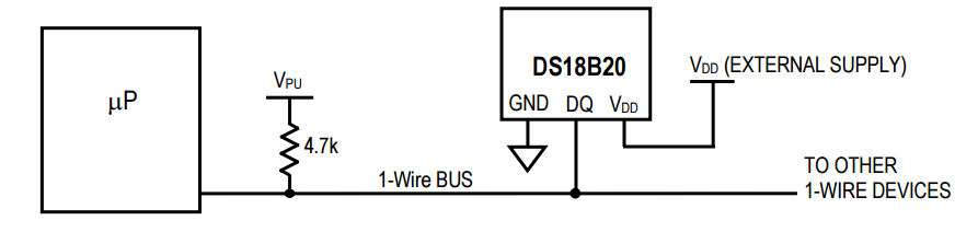
V power - usually 3.3V for the Pi
Ground
and
Data
The pull up resistor varies according to the device but anything from 2.2K to 4.7K Ohms works.
There can be multiple devices on the bus and each one has a unique 64-bit lasered ROM code, which can be used as an address to select the active devices.
For simplicity, it is better to start off with a single device and avoid the problem of enumerating the devices on the bus - although once you know how everything works this isn't difficult to implement.
So to get started select a 1-wire device that you want to work with and set it up ready to talk to the Pi of your choice. In the next chapter we show how to work with an iButton and in the following chapter the DS18B20 is explained. The functions described in this chapter should work with any 1-wire device.
Initialization
Every transaction with the a 1-wire device starts with an initialization handshake.
First we have to work out how to configure the GPIO line. This example assumes that the 1-wire device is connected to pin 7. If this isn't the case change the pin enumeration to the correct pin. For a full practical example see either of the next two chapters.
You might think that we have to initialize the GPIO line so that it works in pull up mode.
This isn't necessary and the default push pull mode will do.
The reason is that in the case of the 1-wire bus the master controls when other devices send their data. Typically the master sends a pulse and then the slaves respond by pulling the line low. As long as the master doesn't drive the line during the period when the slaves are responding everything is fine.
What we do in practice is to configure the GPIO line for output only when the master needs to drive the line. Once the master is finished the GPIO line is set back to input and the pull up resistor is allowed to pull the line back up. After this any slave wanting to send data is free to pull the line low.
The first transaction we need is the initialization pulse.
This is simply a low pulse that lasts at least 480 microseconds, a 15 to 60 microsecond pause follows and then any and all of the devices on the bus pull the line low for 60 to 240 microseconds.
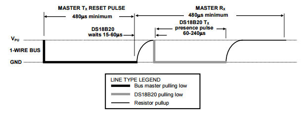
The suggested timings are:
low for 480 microseconds and read the line after 70 microsecond followed by a 410 pause.
This is fairly easy to implement as a function:
int presence(uint8_t pin) {
    bcm2835_gpio_fsel(pin, BCM2835_GPIO_FSEL_OUTP);
    bcm2835_gpio_write(pin, LOW);
    bcm2835_delayMicroseconds(480);
    bcm2835_gpio_fsel(pin, BCM2835_GPIO_FSEL_INPT);
    bcm2835_delayMicroseconds(70);
    uint8_t b = bcm2835_gpio_lev(pin);
    bcm2835_delayMicroseconds(410);
    return b;
}
We pull the line low for 480 microseconds and then let it be pulled back up by changing the line to input i.e. high impedance. After a 70 microsecond wait which is right at the start of the guaranteed period when the line should be low if there is an active device on the bus we read the input line and then wait another 410 microseconds to complete the data slot.
The timings in this case are not critical as long as the line is read while it is held low by the slaves - which is never less than 60 microseconds and is typically as much as 100 microseconds.
The actual pulse timings with the values given are 483 microsecond reset and a total slot time of 632 microseconds.
If there is a device the function should return zero and if there are no devices it should return a one.
if(presence(RPI_GPIO_P1_07)==1){
 printf("No device \n");
}
If you try this partial program and have a logic analyzer with a 1-wire protocol analyzer you will see something like:

Seeing a presence pulse is the simplest and quickest way to be sure that your hardware is working.
Writing Bits
Our next task is to implement the sending of some data bits to the device.
The 1-wire bus has a very simple data protocol.
All bits are sent using a minimum of 60 microseconds for a read/write slot. Each slot must be separated from the next by a minimum of 1 microsecond.
The good news is that timing is only critical within each slot. You can send the first bit in a time slot and then take your time before you send the next bit - the device will wait for you. This means you only have to worry about timing within the functions that read and write individual bits.
To send a zero you have to hold the line low for most of the slot.
To send a one you have to hold the line low for just between 1 and 15 microseconds and leave the line high for the rest of the slot.
The exact timings can be seen below;

It seems reasonable to use the typical timing given in the data sheets.
So for a zero we hold the line low for 60 microsecond then let it go high for the remainder of the slot 10 microseconds.
To send a one we hold the line for 6 microsecond and then let it go high for the remainder of the slot 64 microseconds.
As the only time critical operations are the actual setting of the line low and then back to high there is no need to worry too much about speed of operation of the entire function so we might as well combine writing 0 and 1 into a single writeBit function:
void writeBit(uint8_t pin,int b) {
    int delay1, delay2;
    if (b == 1) {
        delay1 = 6;
        delay2 = 64;
    } else {
        delay1 = 80;
        delay2 = 10;
    }
    bcm2835_gpio_fsel(pin, BCM2835_GPIO_FSEL_OUTP);
    bcm2835_gpio_write(pin, LOW);
    bcm2835_delayMicroseconds(delay1);
    bcm2835_gpio_fsel(pin, BCM2835_GPIO_FSEL_INPT);
    bcm2835_delayMicroseconds(delay2);
}
The code at the start of the function simply increases the time between slots slightly. Notice that once again we return the GPIO line to input i.e. high impedance rather than driving the line high at the end of the transaction. This allows the line to be pulled high ready for any response from the slave.
You can see two ones followed by two zeros in the following logic analyzer trace:

A First Command - Writing Bytes
After discovering that there is at least one device connected to the bus the master has to issue a ROM command. In many cases the ROM command used first will be the Search ROM command which enumerates the 64-bit codes of all of the devices on the bus. After collecting all of these codes the master can used the Match ROM commands with a specific 64-bit code to select the device the master wants to talk to.
While it is perfectly possible to implement the Search ROM procedure it is simpler to work with the single device by using commands which ignore the 64-bit code and address all of the devices on the bus at the same time.
Of course this only works as long as there is only one device on the bus.
If there is only one device then we can use the Skip ROM command 0xCC to tell all the devices on the bus to be active.
We now need a function that can send a byte.
As we have a writeBit function this is easy:
void sendskip(uint8_t pin){ writeBit(pin,0); writeBit(pin,0); writeBit(pin,1); writeBit(pin,1);writeBit(pin,0); writeBit(pin,0); writeBit(pin,1); writeBit(pin,1); }
Notice that 0xCC is 1100 1100 in binary and the 1-wire bus sends the least significant bit first.
If you try this out you should find it works but device doesn't respond because it is waiting for another command.
Again as the time between writing bits isn't critical we can take this first implementation of the function and write something more general if slightly slower.
The writeByte function will write the low 8 bits of an int to the device:
void writeByte(uint8_t pin,int byte) {
    int i;
    for (i = 0; i < 8; i++) {
        if (byte & 1) {
            writeBit(pin,1);
        } else {
            writeBit(pin,0);
        }
        byte = byte >> 1;
    }
}
Using this we can send a Skip ROM command using:
writeByte(RPI_GPIO_P1_07,0xCC);
You can see the pattern of bits sent on a logic analyzer:
Reading Bits
We already know how the master sends a one and a zero the protocol for the slave device is exactly the same except that the master still provides the slots starting pulse.
That is the master starts a 60 microsecond slot by pulling the bus down for a bit more than 1 microsecond. Then the slave device either holds the line down for a further 15 microseconds minimum or it simply allows the line to float high. See below for the exact timings:

So all we have to do to read bits is to pull the line down for just a bit more than 1 microsecond and then sample the bus after a pause.
The data sheet gives 6 microseconds for the master's pulse and a 9 microsecond pause. In practice a final delay of 8 microseconds seems to work best and allows for the time to change the line's direction.
uint8_t readBit(uint8_t pin) {
    bcm2835_gpio_fsel(pin, BCM2835_GPIO_FSEL_OUTP);
    bcm2835_gpio_write(pin, LOW);
    bcm2835_delayMicroseconds(6);
    bcm2835_gpio_fsel(pin, BCM2835_GPIO_FSEL_INPT);
    bcm2835_delayMicroseconds(8);
    uint8_t b = bcm2835_gpio_lev(pin);
    bcm2835_delayMicroseconds(55);
    return b;
}
A logic analyzer shows the typical pattern of bits from the device:
Finally we need a function that will read a byte. As in the case of writing a byte there is no time criticality in the time between reading bits so we don't need to take extra special care in constructing the function;
int readByte(uint8_t pin) {
    int byte = 0;
    int i;
    for (i = 0; i < 8; i++) {
        byte = byte | readBit(pin) << i;
    };
    return byte;
}
The only difficult part is to remember that the 1-wire bus sends the least significant bit first and so this has to be shifted into the result from the right.
This is the final function we need. Now we can:
-
test to see if a device is present.
presence(uint8_t pin)
-
write a byte
void writeByte(uint8_t pin,int byte) -
read a byte
int readByte(uint8_t pin)
These functions will be used in the next two chapters to work with two real 1-wire devices.
These are not the only functions we need to work with the 1-wire bus. We need to be able to compute the CRC error checks that are commonly used to confirm that data has been transmitted correctly and we need to perform a ROM search to discover what devices are connected to the bus.
Now On Sale!
You can now buy a print or ebook edition of Raspberry Pi IoT in C from Amazon.
For Errata and Listings Visit: IO Press
This our ebook on using the Raspberry Pi to implement IoT devices using the C programming language. The full contents can be seen below. Notice this is a first draft and a work in progress.
Chapter List
-
Introducing Pi (paper book only)
-
Getting Started With NetBeans In this chapter we look at why C is a good language to work in when you are creating programs for the IoT and how to get started using NetBeans. Of course this is where Hello C World makes an appearance.
-
First Steps With The GPIO
The bcm2835C library is the easiest way to get in touch with the Pi's GPIO lines. In this chapter we take a look at the basic operations involved in using the GPIO lines with an emphasis on output. How fast can you change a GPIO line, how do you generate pulses of a given duration and how can you change multiple lines in sync with each other? -
GPIO The SYSFS Way
There is a Linux-based approach to working with GPIO lines and serial buses that is worth knowing about because it provides an alternative to using the bcm2835 library. Sometimes you need this because you are working in a language for which direct access to memory isn't available. It is also the only way to make interrupts available in a C program. -
Input and Interrupts
There is no doubt that input is more difficult than output. When you need to drive a line high or low you are in command of when it happens but input is in the hands of the outside world. If your program isn't ready to read the input or if it reads it at the wrong time then things just don't work. What is worse is that you have no idea what your program was doing relative to the event you are trying to capture - welcome to the world of input. -
Memory Mapped I/O
The bcm2835 library uses direct memory access to the GPIO and other peripherals. In this chapter we look at how this works. You don't need to know this but if you need to modify the library or access features that the library doesn't expose this is the way to go. -
Near Realtime Linux
You can write real time programs using standard Linux as long as you know how to control scheduling. In fact it turns out to be relatively easy and it enables the Raspberry Pi to do things you might not think it capable of. There are also some surprising differences between the one and quad core Pis that make you think again about real time Linux programming. -
PWM
One way around the problem of getting a fast response from a microcontroller is to move the problem away from the processor. In the case of the Pi's processor there are some builtin devices that can use GPIO lines to implement protocols without the CPU being involved. In this chapter we take a close look at pulse width modulation PWM including, sound, driving LEDs and servos. -
I2C Temperature Measurement
The I2C bus is one of the most useful ways of connecting moderately sophisticated sensors and peripherals to the any processor. The only problem is that it can seem like a nightmare confusion of hardware, low level interaction and high level software. There are few general introductions to the subject because at first sight every I2C device is different, but here we present one. -
A Custom Protocol - The DHT11/22
In this chapter we make use of all of the ideas introduced in earlier chapters to create a raw interface with the low cost DHT11/22 temperature and humidity sensor. It is an exercise in implementing a custom protocol directly in C. -
One Wire Bus Basics
The Raspberry Pi is fast enough to be used to directly interface to 1-Wire bus without the need for drivers. The advantages of programming our own 1-wire bus protocol is that it doesn't depend on the uncertainties of a Linux driver. -
iButtons
If you haven't discovered iButtons then you are going to find of lots of uses for them. At its simples an iButton is an electronic key providing a unique coce stored in its ROM which can be used to unlock or simply record the presence of a particular button. What is good news is that they are easy to interface to a Pi. -
The DS18B20
Using the software developed in previous chapters we show how to connect and use the very popular DS18B20 temperature sensor without the need for external drivers. -
The Multidrop 1-wire bus
Some times it it just easier from the point of view of hardware to connect a set of 1-wire devices to the same GPIO line but this makes the software more complex. Find out how to discover what devices are present on a multi-drop bus and how to select the one you want to work with. -
SPI Bus
The SPI bus can be something of a problem because it doesn't have a well defined standard that every device conforms to. Even so if you only want to work with one specific device it is usually easy to find a configuration that works - as long as you understand what the possibilities are. -
SPI MCP3008/4 AtoD (paper book only)
-
Serial (paper book only)
-
Getting On The Web - After All It Is The IoT (paper book only)
-
WiFi (paper book only)
Related Articles
Real Raspberry Pi - Getting Started And Custom NOOBS