The bcm2835C library is the easiest way to get in touch with the Pi's GPIO lines. In this chapter we take a look at the basic operations involved in using the GPIO lines with an emphasis on output. How fast can you change a GPIO line, how do you generate pulses of a given duration and how can you change multiple lines in sync with each other?
Now On Sale!
You can now buy a print or ebook edition of Raspberry Pi IoT in C from Amazon.
For Errata and Listings Visit: IO Press
This our ebook on using the Raspberry Pi to implement IoT devices using the C programming language. The full contents can be seen below. Notice this is a first draft and a work in progress.
Chapter List
-
Introducing Pi (paper book only)
-
Getting Started With NetBeans In this chapter we look at why C is a good language to work in when you are creating programs for the IoT and how to get started using NetBeans. Of course this is where Hello C World makes an appearance.
-
First Steps With The GPIO
The bcm2835C library is the easiest way to get in touch with the Pi's GPIO lines. In this chapter we take a look at the basic operations involved in using the GPIO lines with an emphasis on output. How fast can you change a GPIO line, how do you generate pulses of a given duration and how can you change multiple lines in sync with each other? -
GPIO The SYSFS Way
There is a Linux-based approach to working with GPIO lines and serial buses that is worth knowing about because it provides an alternative to using the bcm2835 library. Sometimes you need this because you are working in a language for which direct access to memory isn't available. It is also the only way to make interrupts available in a C program. -
Input and Interrupts
There is no doubt that input is more difficult than output. When you need to drive a line high or low you are in command of when it happens but input is in the hands of the outside world. If your program isn't ready to read the input or if it reads it at the wrong time then things just don't work. What is worse is that you have no idea what your program was doing relative to the event you are trying to capture - welcome to the world of input. -
Memory Mapped I/O
The bcm2835 library uses direct memory access to the GPIO and other peripherals. In this chapter we look at how this works. You don't need to know this but if you need to modify the library or access features that the library doesn't expose this is the way to go. -
Near Realtime Linux
You can write real time programs using standard Linux as long as you know how to control scheduling. In fact it turns out to be relatively easy and it enables the Raspberry Pi to do things you might not think it capable of. There are also some surprising differences between the one and quad core Pis that make you think again about real time Linux programming. -
PWM
One way around the problem of getting a fast response from a microcontroller is to move the problem away from the processor. In the case of the Pi's processor there are some builtin devices that can use GPIO lines to implement protocols without the CPU being involved. In this chapter we take a close look at pulse width modulation PWM including, sound, driving LEDs and servos. -
I2C Temperature Measurement
The I2C bus is one of the most useful ways of connecting moderately sophisticated sensors and peripherals to the any processor. The only problem is that it can seem like a nightmare confusion of hardware, low level interaction and high level software. There are few general introductions to the subject because at first sight every I2C device is different, but here we present one. -
A Custom Protocol - The DHT11/22
In this chapter we make use of all of the ideas introduced in earlier chapters to create a raw interface with the low cost DHT11/22 temperature and humidity sensor. It is an exercise in implementing a custom protocol directly in C. -
One Wire Bus Basics
The Raspberry Pi is fast enough to be used to directly interface to 1-Wire bus without the need for drivers. The advantages of programming our own 1-wire bus protocol is that it doesn't depend on the uncertainties of a Linux driver. -
iButtons
If you haven't discovered iButtons then you are going to find of lots of uses for them. At its simples an iButton is an electronic key providing a unique coce stored in its ROM which can be used to unlock or simply record the presence of a particular button. What is good news is that they are easy to interface to a Pi. -
The DS18B20
Using the software developed in previous chapters we show how to connect and use the very popular DS18B20 temperature sensor without the need for external drivers. -
The Multidrop 1-wire bus
Some times it it just easier from the point of view of hardware to connect a set of 1-wire devices to the same GPIO line but this makes the software more complex. Find out how to discover what devices are present on a multi-drop bus and how to select the one you want to work with. -
SPI Bus
The SPI bus can be something of a problem because it doesn't have a well defined standard that every device conforms to. Even so if you only want to work with one specific device it is usually easy to find a configuration that works - as long as you understand what the possibilities are. -
SPI MCP3008/4 AtoD (paper book only)
-
Serial (paper book only)
-
Getting On The Web - After All It Is The IoT (paper book only)
-
WiFi (paper book only)
The bcm2835 library is designed to make it easy to access the hardware - there are other ways that we will examine later. It has the advantage of being open source and it uses a direct approach so you don't need to worry about Linux drivers.
In this chapter we take a first look at using bcm2835, how to install it and how to control the GPIO pins as basic input output lines. Later on we will look at how the library works and how to avoid using it if you really need to.
Setting Up bcm2835 With NetBeans
Exactly how to set up the library is a tiny bit tricker than most because it has to run as root to be able to access all of the GPIO facilities. It is also a little puzzling how to set up the library if you are using a remote build server - where do you copy the library for example? As it turns out the answer to this is easy.
First we need to set up a password for the stanard root user and allow the root user to log in using SSH.
To allow root to log on with a password we have to assign a password so log in as user pi and give the command:
sudo passwd root
you will be prompted to type the new password twice.
Next use a text editor of your choice e,g nano to edit the ssh.config file to allow root to log on via SSH:
sudo nano /etc/ssh/sshd_config
Find
PermitRootLogin without-password
and change it to read
PermitRootLogin yes
Reboot the system to make the changes take effect or restart the SSH agent:
sudo service ssh restart
Check that this works by logging on using SSH, Putty say, using the user name root and the password you supplied earlier.
If you are using NetBeans on the Pi then simply log in as root when ever you are working with it.
If you are using NetBeans with the Pi as a remote build host then you need to create a new build host with the user name root and the password you specified. This might have the side effect of moving the location where projects are created to root's home directory.
With these changes you can check that you can create and/or run a project with the new build host.
If you find that a project is simply failing to run and returns a -1 status with no reason given the chances are you are not runing the program as root.
The final step is to download the bcm2835 library from:
http://www.airspayce.com/mikem/bcm2835/
At the time of writing this is at version 1.50 and works with all versions of the Raspberry Pi including the Zero and the Pi 3.
To install the library you need to download it into root's home directory. You can do this from the command line using:
sudo wget "http://www.airspayce.com/mikem/bcm2835/bcm2835-1.50.tar.gz"
Where you may well need to change the URL to reflect the latest version. The wget command as given will download the tar ball into the current directory.
Then use the following commands:
tar zxvf bcm2835-1.xx.tar.gzcd bcm2835-1.xx./configuremakesudo make checksudo make install
where xx is the version number, 50 at the moment. When these commands are completed you will have a bcm2835-1.xx folder which contains copies of the library, the header file and all the source code.
The library and header file that you are going to use will have been installed in /usr/local/lib and /user/local/include where NetBeans will find them automatically. Notice that NetBeans will find them automatically even if you are using the Pi as a remote build host.
That is you do not have to install the library on the machine running NetBeans only on the build host.
To make use of the library in your program you have to do two final things.
The first is you have to include the header file:
#include <bcm2835.h>
NetBeans will not only find the header on the remote build host it will also let you work with it as if it was a file within the project.
You also have to specify the name of the library that you want the linker to add to your program. To do this right click on the project and select properties. Select Build,Linker in the dialog box that appears, click the three dots in the Libraries section, click Add Library and specify bcm2835. Don't make the mistake of trying to add a Library File.
Note you don't have to specify where the library is stored or it version number NetBeans will work it out.
Now you are ready to write your first IoT program which is nearly always to flash an LED.
A First IoT Program
This purpose of this program is to just let you check that everything is working - the functions used will be explained in detail later.
Start a new project, call it Blink, and make sure you add the bcm2835 library to the linker options - right click on the project and select properties, select Build,Linker in the dialog box that appears, click the three dots in the Libraries section, click Add Library and specify bcm2835.
Then enter the program:
#include <bcm2835.h> #include <stdio.h>int main(int argc, char **argv) { if (!bcm2835_init()) return 1; bcm2835_gpio_fsel(RPI_GPIO_P1_07, BCM2835_GPIO_FSEL_OUTP); while (1) { bcm2835_gpio_write(RPI_GPIO_P1_07, HIGH); bcm2835_delay(500); bcm2835_gpio_write(RPI_GPIO_P1_07, LOW); bcm2835_delay(500); } bcm2835_close(); return 0; }
Don't panic when NetBeans initially shows you lots of errors. If you build or run the project NetBeans will take notice of the header files and stop worrying about identifiers like bcm2835_init(). Once the project has been built NetBeans knows all about the new library and will syntax check and offer code completion hints.
Even though you don't know much about the library just yet you can see that the general idea. First we try to initalize the library. If this works GPIO pin 7 is set to be an output and then the loop turns it on and off (high voltage then low) with a dearly of half a second.
The library uses physical pins rather than logical GPIO numbers so RPI_GPIO_P1_07 is pin 7 on connector P1.

If you want to connect an LED to see the "blinking" for real then this is easy enough but you do need a current limiting resistor - 270Ohm is a good choice.
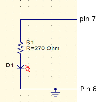
How you build the circuit is up to you. You can use a prototyping board or just a pair of jumper wires.

If you can't be bothered to go though the ritual of testing "blinky" with a real LED then just connect a logic analyzer to pin 7 and you will see the one second pulses.
Running Programs On NetBeans
All you have to do to run the program is click the Run icon or press F6. This downloads the program to the Pi that is the Build Server for the project and then runs it on the same Pi. If you try this with Blink you will see the LED blink or the Logic Analyzer will show the output pulse train.
The next question is how do you stop the program.
If the program isn't in the form of an infinite loop it will terminate naturally and there isn't anything to do but blink is an infinite loop which never ends. If you click the run icon a second time a second copy of the program will be created and will start to run.
This clearly isn't a good idea for programs that are interacting with GPIO lines.
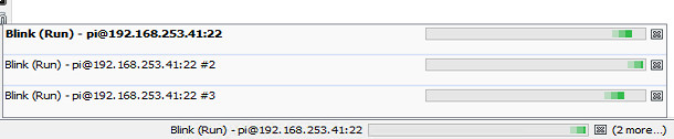
You have to explicitly stop the program before you run it again. To do this simply click the red stop button down in the output window:
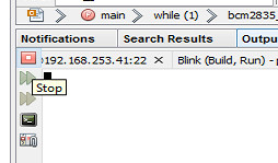
You can also see that there is a program running from the status bar at the bottom of the window:

If you do run multiple programs, either by design or accident, you can stop any of them by double clicking on the run status at the bottom of the window. Notice that the message to the right tells you how many programs are running. You can stop any or all by clicking on the corresponding stop buttons.
This is the minimum you need to know to run a program using NetBeans. The important topics of debugging and creating templates will be discussed in a later chapter.
Pin Numbering
The one thing that drives every programmer mad are the different ways of referring to the numbering of the GPIO pins.
There is the physical pin number i.e. the number of the pin on the physical connector and the logical GPIO number that is assigned deep in the hardware.
Another problem is that different generations of Pi have modified the pin layout slightly and there was an extension in the move from Pi 1 to Pi 2 and 3. In most cases the changes are slight and if you stay within the first 26 pins of the GPIO connector then you don't even have to worry if your program is running on a Pi 1, 2 or 3.
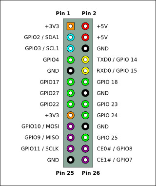
The standard connector for a late generation P1 is:
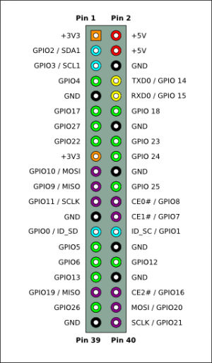
and for a Pi 2 or 3:
The bcm2835 library works in terms of the GPIO numbers defined by the processor. However it also provides an enumeration which allows you to work in terms of the physical pins. For example in the blinky program the instruction:
bcm2835_gpio_write(RPI_GPIO_P1_07, HIGH);
set the GPIO line connected to pin 7 on connector P1 high. If you look at the code for the enumeration you will discover that RPI_GPIO_P1_07 is defined to be 4 which corresponds to GPIO 4 which is indeed connected to pin 7. You could have used:
bcm2835_gpio_write(4, HIGH);
to set the same GPIO line high.
It is up to you which way you choose to specify pin numbers - by logical GPIO number or physical pin number. In most cases the physical pin numbers are more direct because they specify what you are actually connecting wires to. However notice that you do need to specify the model of Pi that you are working with. For example the library defines three types of pin 3 RPI_GPIO_P1_03 which is the Pi 1 revision 1 version of pin 3 or GPIO 0 and RPI_V2_GPIO_P1_03 which is the Pi 1 revision 2 version of pin 3 or GPIO 2 and RPI_BPLUS_GPIO_J8_03 for all models after the B+.
You can see that this can be confusing but the change in the pin outs is also confusing. If you are using the Pi Compute module then don't just he enumeration simply use the GPIO number.
In general you have to decide if you should use enumeration values that start with
RPI_GPIO for Pi 1 revision 1
RPI_V2_GPIO for Pi 1 revision 2
or
RPI_BPLUS_GPIO for all modern Pis from the B+ on.
Drive Characteristics
The characteristics of the Pi's I/O lines are quite complicated and best tackled in stages.
All of the GPIO lines can either be used as general purpose GPIO lines or a dedicated alternative purpose such as implementing a UART - serial interface etc.
In this and closely following chapters the subject is the general purpose GPIO lines. Later chapters deal with alternate uses.
What we are concerned with in this chapter is just the basic configuration of a GPIO line.
The key features is that as an input the GPIO line is high impedance - you can effectively ignore it when you connect to another circuit.
In output mode a single GPIO line can source and sink 16mA.
Unfortunately the Pi power supply can only supply enough power for all of the GPIO lines working at 3mA each. If you use too much current drive then the 3.3V supply will fail. For a Pi 1 the limit is around 50mA in total and for a Pi 2 and later then you can draw 100mA. However when you get close to these limits you might find that current spikes cause strange behavior.
In practice if you are planing to use more than 3mA from multiple GPIO lines consider using a transistor. If your circuits draw more than 50 or 100mA from the 3.3V supply rail consider a separate power supply. You can use the 5V supply with a regulator if you need more 3.3V current.
Notice that there is a subtle distinction here between current supplied by a GPIO line - which should always be less than 16mA and the current taken from the 3.3V power supply which should be less than 100mA.
The situation is complicated because the amount of power the Pi takes from the 3.3V supply depends on what peripherals it is using.
Notice that the 16mA limit means that you cannot safely drive a standard 20mA red LED without restricting the current to below 16mA. A better solution is to use a low power 2mA LED.
Finally it is worth mentioning that the GPIO line can be configured to use push-pull, pull up or pull down drive. In addition you can set the strength of the drive. More of this later.
Output
The bcm2835 functions that you need to make use of a pin in output mode are very simple.
The basic configuration function is:
void bcm2835_gpio_fsel (uint8_t pin, uint8_t mode)
This will set a pin specified by GPIO number to a given mode. The two most commonly use modes are:
BCM2835_GPIO_FSEL_INPTBCM2835_GPIO_FSEL_OUTP
These set the GPIO line to either input or output.
So to set the GPIO line connected to pin 7 on a Pi B+ or later you would use:
bcm2835_gpio_fsel(RPI_BPLUS_GPIO_J8_07, BCM2835_GPIO_FSEL_OUTP);
Once you have set the line to output there are a range of ways to set its state to high or low voltage output. The number of possibilities is initially confusing but they each have their particular use.
The simplest and most often used is:
void bcm2835_gpio_write (uint8_t pin, uint8_t on)
As always you specify the GPIO number or use one of the Physical pin enumeration values. The on parameter can be either
HIGH
or
LOW
So to set the GPIO line on pin 7 to high you would use:
bcm2835_gpio_write(RPI_BPLUS_GPIO_J8_07, HIGH);
and to set it low:
bcm2835_gpio_write(RPI_BPLUS_GPIO_J8_07, LOW);
As HIGH is defined to be 1 and LOW 0 you can also write
bcm2835_gpio_write(RPI_BPLUS_GPIO_J8_07, 1);
and use a variable is you want to:
  int state=1;
  bcm2835_gpio_write(RPI_BPLUS_GPIO_J8_07, state);
Write is useful when you want to call a single function and set the state of the line. However there are times when you always want to set a line high or low. In this case you can use one of:
void bcm2835_gpio_set (uint8_t pin)void bcm2835_gpio_clr (uint8_t pin)
As you can guess set sets the line to high and clr sets the line low. For example to set pin 7 high:
void bcm2835_gpio_set (RPI_BPLUS_GPIO_J8_07);
Multi Functions
So far the functions have allowed us to change one line at at time. If you want to change more than one line then there are "multi" equivalents of the write, set and clr functions:
void bcm2835_gpio_write_multi (uint32_t mask, uint8_t on)
void bcm2835_gpio_set_multi (uint32_t mask)
void bcm2835_gpio_clr_multi (uint32_t mask)
In this case you have to supply a "mask" to indicate which GPIO lines are to be altered. The mask is very simple each of the 32 bits in the mask represent a GPIO line - bit zero is for GPIO 0, bit one is for GPIO 1 and so on. Of course the problem here is that you can select GPIO lines that aren't brought out on the Pi's connector and which GPIO corresponds to which pin? Fortunately it is very easy to automatically make up a mask that corresponds to any set of GPIO lines specified by pin number. Suppose you want a mask for pin 3 then this means you need to set the third bit in the mask. This can be done using 1<<3 i.e. 1 shifted three places to the left - i.e. this is the mask you require and it it a general algorithm.
If you want a masks for pin n all you have to do is
1<<n
Now suppose you want a mask for pin n and pin m. All you have to do is or the masks for each pin together so the complete mask is:
(1<<n) | (1<m)
Of course you can use the pin enumeration in place of pin numbers so to create a mask for pin 3 and pin 5 you would use:
uint32_t mask=(1 << RPI_GPIO_P1_03) | (1 << RPI_GPIO_P1_05);
Once you have the mask you can use it in any of the multi functions. For example:
bcm2835_gpio_set_multi (mask);
sets both pin 3 and pin 5 to high in one operation.
There is another mask function which can be used to set multiple GPIO lines to different values:
void bcm2835_gpio_write_mask (uint32_t value, uint32_t mask)
In this case the mask parameter works in the same way and specifies which GPIO lines are to be involved. The difference is that the value parameter determines what each of the lines is to be set to. So for example if bit 6 of the mask is a 1 then GPIO line 6 will be set to whatever bit 6 of the value parameter is. This allows you to set multiple GPIO lines to different states. For example
uint32_t mask=(1 << RPI_GPIO_P1_03) | (1 << RPI_GPIO_P1_05);
uint32_t value=1<< RPI_GPIO_P1_05);
bcm2835_gpio_write_mask (value, mask);
Will set pin 3 to low and pin 5 to high because the mask specifies these pins and in value the bit corresponding to pin 3 is low and the bit corresponding to pin 5 is high. Notice the state of bits in value that do not correspond to bits set to 1 in mask have no effect.
The mask function are very useful when you want coordinated changes across a number of GPIO lines.
Drive Characteristics
The GPIO output can be configured into one of a number of modes but the most important is pull-up/down.
Before we get to the code to do the job it is worth spending a moment explaining the three basic output modes.
In pushpull mode two transistors of opposite polarity are used, for example:
The circuit behaves like the two-switch equivalent shown on the right. Only one of the transistors, or switches is "closed" at any time. If the input is high then Q1 is saturated and the output is connected to ground - exactly as if S1 was closed. If the input is low then Q2 is saturated and it is as if S2 was closed and the output is connected to 1.8V.
You can see that this pushes the output line high with the same "force" as it pulls it low.
This is the standard configuration for a GPIO output.
The pullup mode replaces one of the transistors by a resistor:
In this case the circuit is equivalent to having a single switch. When the switch is closed the output line is connected to ground and hence driven low. When the switch is open the output line is pulled high by the resistor.
You can see that in this case the degree of pulldown is greater than the pullup, where the current is limited by the resistor. The advantage of this mode is that it can be used in an AND configuration. If multiple gpio or other lines are connected to the output, then any one of them being low will pull the output line low. Only when all of them are off does the resistor succeed in pulling the line high.
This is used, for example, in a serial bus configuration like the I2C bus.
Finally the pulldown mode is exactly the same as the pullup only now the resistor is used to pull the output line low:
In the case of the pulldown mode the line is held high by the transistor but pulled low by the resistor only when all the switches are open. Putting this the other way round - the line is high if any one switch is closed.
Generally speaking the pushpull mode is best for driving general loads, motors, LEDs, etc.
The pullup/down modes are used where you need to create a serial bus of some sort or when the load needs this sort of drive.
To set the mode for a GPIO line the simplest function to use is:
bcm2835_gpio_set_pud (uint8_t pin, uint8_t pud)
where the pin is specified in the usual way and pud can be any of:
BCM2835_GPIO_PUD_OFF
BCM2835_GPIO_PUD_DOWN
BCM2835_GPIO_PUD_UP
Off is the default and you have to explicitly set down and up if required.
The internal pullup/down resistors are in the range 50K to 65K Ohms. There are also external 1.8K Ohm pull ups on pins 3 and 5. The only way to remove these pull ups is to unsolder the resistors from the board.
How Fast?
A fundamental question that you have to answer for any processor intended for use in embedded or IoT projects is - how fast can the GPIO lines work?
Some times the answer isn't of too much concern because what you want to do only works relatively slowly. Any application that is happy with response times in the tens of millisecond region will generally work with almost any processor. However if you want to implement custom protocols or anything that needs microsecond responses the question is much more important.
It is fairly easy to find out how fast a single GPIO line can be used if you have a logic analyzer or oscilloscope. All you have to do is run the program:
bcm2835_gpio_fsel(RPI_BPLUS_GPIO_J8_07, BCM2835_GPIO_FSEL_OUTP);
for(;;) {
 bcm2835_gpio_write(RPI_BPLUS_GPIO_J8_07, HIGH);
 bcm2835_gpio_write(RPI_BPLUS_GPIO_J8_07, LOW);
}
What you will see depends on which version of the Pi you are working with.
The pulse widths are:
| Pi |
pulse width (micro seconds) |
|
| Zero | 0.0625 to 0.125 | |
| 1 | ||
| 2 | 0.0625 to 0.125 | |
| 3 |
The pulses generated are not very even - a few short 0.0625 pulses and one longer 0.125 microsecond pulse. This is presumably due to the way the CPU executes the instructions.It seems that the 0.124 pulse is generated by a 0.0625 pulse being missed every 1.56 microseconds.
You will also see a regular interruption to the pulse train every 0.125ms (Pi 2) and few much bigger interruptions every few milliseconds depending on the loading of the processor. More about the way CPU loading effects program in the chapter on Near Real Time Linux.
it also doesn't make any difference if you use set and clr or any of the other functions. You can also use a while(1) loop in place of the for loop - it makes no difference to the overall timing.
So you can generate nano-second pulses using the Pi but not very accurately. For accuracy you have to move to the microsecond range which is usually sufficient for most applications.
usleep & delayMicroseconds
To generate pulses of a known duration we need to pause the program between state changes.
The simplest way of sleeping a thread for a number of microseconds is to use usleep - even if it is deprecated in Posix.
To try this, include a call to usleep(10) to delay the pulse:
for(;;)
{
 bcm2835_gpio_set(RPI_BPLUS_GPIO_J8_07);
 usleep(10);
 bcm2835_gpio_clr(RPI_BPLUS_GPIO_J8_07);
 usleep(10);
}
You will discover that adding usleep(10) doesn't increase the pulse length by 10 microseconds but by around 80 microseconds. You will also discover that longer glitches have gone.
What seems to be happening is that calling usleep yields the thread to the operating system and this incurs an additional 74 microsecond penalty due to calling the scheduler. There are also losses that are dependent on the time you set to wait - usleep only promises that your thread will not restart for at least the specified time.
If you look at how the delay time relates to the average pulse length things seem fairly simple

The equation of the line is approximately
pulse length = delay+74
What this means is that if you want to set a delay less than 74 microseconds don't use usleep.
The same isn't true of the delayMicroseconds function
void bcm2835_delayMicroseconds
This uses a busy wait loop for times shorter than 450 microseconds and a system delay like usleep for longer periods.
We first need to look at how a busy wait works.
Busy Wait
For pulses of less than about 100 microseconds it is better to use a busy wait i.e. a loop that does nothing. You have to be a little careful about how you insert a loop that does nothing because optimizing compiler have a tendency to take a null loop out in an effort to make your program run faster.
To stop an optimizing from removing busy wait loops make sure you always declare loop variables as volatile.
To generate a pulse of a given length you can use
volatile int i;
for(;;)
{
    for(i=0;i<n;i++){};
    bcm2835_gpio_write(RPI_BPLUS_GPIO_J8_07, HIGH);
    for(i=0;i<n;i++){};
    bcm2835_gpio_write(RPI_BPLUS_GPIO_J8_07, LOW);
 }
Where n is set to a value that depends on the machine it is running on.
For the Pi 2 or Pi Zero for t greater than or equal to 0.5 microseconds you can work out n using
n = 100 * t
with t in microseconds. Below 0.5 you can use
n = 116*t - 9.3
but pulse length isn't reliable.
For example if you want 1 microsecond pulses on a Pi 2 then n=100 and the result can be seen below:

Notice that the pulses vary from about 0.93 to 1 microsecond but this is accurate enough for most applications.
| Pi | t>=0.5 |
| Zero | 100*t |
| 2 | 100*t |
Automatic Busy Wait Calibration
It is usually said that the big problem with using busy waits is that they depend on how fast the CPU is working. The other big problem with them is that they lock up the CPU and stop it from doing anything else, but this is a minor problem with a multicore processor.
You can set constants at the start of a program to allow it to work with different versions of the Pi but it is also fairly simple to add a calibration routine. All you have to do is time how long a set number of loops take and then work out how many loops you need for a busy wait of 1 microsecond and use this to derive all other delay times.
For example:
#include <stdio.h>
#include <stdlib.h>
#include <bcm2835.h>
#include <time.h>

#define BILLION 1000000000L

int main(int argc, char** argv) {
    struct timespec btime, etime;

    volatile int i;
    clock_gettime(CLOCK_REALTIME, &btime);
    for (i = 0; i < 10000000; i++) {
    };
    clock_gettime(CLOCK_REALTIME, &etime);
    double nseconds = (double) ((etime.tv_sec - btime.tv_sec)* BILLION)+
          (double) (etime.tv_nsec - btime.tv_nsec);
    int n = (int) 10 / nseconds * BILLION + 0.5;
    printf("time = %f (s)  \n \r", nseconds / BILLION);
    printf("n= %d \n\r", n);
    return (EXIT_SUCCESS);
}
If you run this on say a Pi 2 you will see that n=100 i.e. you need 100 busy wait loops to delay for one microsecond.
You can also create a function that does the same job:
int busyWaitCalibrate() {
    struct timespec btime, etime;
    volatile int i;
    clock_gettime(CLOCK_REALTIME, &btime);
    for (i = 0; i < 10000000; i++) {
    };
    clock_gettime(CLOCK_REALTIME, &etime);
    double nseconds = (double) ((etime.tv_sec - btime.tv_sec)
            * 1000000000L)+(double) (etime.tv_nsec - btime.tv_nsec);
     int n = (int) 10 / nseconds * 1000000000L + 0.5;
    return n;
}
Note you need to include time.h to use the function i.e.
#include <time.h>
Also notice that clock_gettime isn't part of the C standard and you have to select program type C in NetBeans to make it work.
If you are going to use busyWaitCalibrate it is a good idea to take a few samples and average them to make sure you get a sensible value for n.
delayMicroseconds
For delays of 1 microsecond up you can avoid all of the problems of calibrating your own busy wait and simply use delayMicroseconds.
For delays of 1 to 450 microseconds this uses a busy wait with an automatic calibration. It simply sits in a loop reading the sytem clock until the required number of microseconds has gone by. Of course this isn't particularly accurate for a short wait and a hand constructed busy wait for loop can be set to create the time delay you want more accurately.
For example on a Pi Zero:
for(;;)
{
 bcm2835_gpio_set(RPI_BPLUS_GPIO_J8_07);
 for(i=0;i<102;i++){};
 bcm2835_gpio_clr(RPI_BPLUS_GPIO_J8_07);
 for(i=0;i<102;i++){};
}
produces pulses that are measured as 0.95 to 1 microsecond.
The equivalent program using delayMicroseconds:
for(;;)
{
 bcm2835_gpio_set(RPI_BPLUS_GPIO_J8_07);
 bcm2835_delayMicroseconds(1);
 bcm2835_gpio_clr(RPI_BPLUS_GPIO_J8_07);
 bcm2835_delayMicroseconds(1);
}
produces pulses that are measured as 0.875 to 1.25.
As you can see the simple busy wait is more accurate and more consistent than delayMicroseconds.
However as the delay increases the errors in delayMicroseconds become less important.
In practice you can generally use delayMicroseconds unless you are generating pulses less than 10 microseconds and need the accuracy.
Phased Pulses
As a simple example of using the bcm2835 output functions lets try to write a short program that pulses two lines - one high and one low and then one low and one high i.e. two pulse trains out of phase by 180 degrees.
The simplest program to do this job is:
#include "bcm2835.h"
#include <stdio.h>
#include <unistd.h>
int main()
{
 bcm2835_init();
 bcm2835_gpio_context pin15 = bcm2835_gpio_init(15);
 bcm2835_gpio_dir(pin15, bcm2835_GPIO_OUT_HIGH);
 bcm2835_gpio_context pin31 = bcm2835_gpio_init(31);
 bcm2835_gpio_dir(pin31, bcm2835_GPIO_OUT_LOW);
 for (;;) {
  bcm2835_gpio_write(pin15, 0);
  bcm2835_gpio_write(pin31, 1);
  bcm2835_gpio_write(pin15, 1);
  bcm2835_gpio_write(pin31, 0);
 }
 return bcm2835_SUCCESS;
}
Notice that there is no delay in the loop so the pulses are produced at the fastest possible speed.
Using a logic analyzer reveals that the result isn't what you might expect:
At this high speed the pulses aren't perfectly regular and come in two sizes but you can also see that the pulse trains are not 180 degrees out of phase. The top train switches on and the bottom train takes about half a pulse before it switches on - the intent is for both actions to occur at the same time.
The point is that it does take quite a long time to access and change the state of an output line.
Of course if we include a delay to increase the pulse width then the delay caused by accessing the GPIO lines in two separate actions isn't so obvious:

In this case the loop now n=1000 busy wait loops:
volatile int i;
for(;;)
{
 bcm2835_gpio_write(RPI_BPLUS_GPIO_J8_07, HIGH);
 bcm2835_gpio_write(RPI_BPLUS_GPIO_J8_11, HIGH);
 for(i=0;i<1000;i++){};
 bcm2835_gpio_write(RPI_BPLUS_GPIO_J8_07, LOW);
 bcm2835_gpio_write(RPI_BPLUS_GPIO_J8_11, LOW);
 for(i=0;i<1000;i++){};
}
You will notice that the pulses are now roughly 10 microseconds wide and they are changing at what looks like nearer to being the same time - of course they aren't.
There is still a lag, but in many applications it might not be important. In other applications it could be crucial.
For example, if the two pulse trains were driving different halves of a motor controller bridge there would be a significant time when both were high - so shorting the power supply. It might only be for 10 microseconds but over time it could well damage the power supply. Of course, any sensible, cautious, engineer wouldn't feed a motor control bridge from two independently generated pulse trains unless they were guaranteed not to switch both sides of the bridge on at the same time.
A better way to generate in phase pulses is to use a multi function and a mask.
For example if you change the first program to:
bcm2835_gpio_fsel(RPI_BPLUS_GPIO_J8_07, BCM2835_GPIO_FSEL_OUTP);
bcm2835_gpio_fsel(RPI_BPLUS_GPIO_J8_11, BCM2835_GPIO_FSEL_OUTP);uint32_t mask=(1 << RPI_GPIO_P1_07) | (1 << RPI_GPIO_P1_11);
for(;;)
{
 bcm2835_gpio_set_multi (mask);
 bcm2835_gpio_clr_multi (mask);
}
Then the two GPIO lines do change at the same time even at the highest speed:

It is clear that if you want to synchronize the changing of GPIO lines you should use the multi functions and a mask.
Can We Do Better?
If by better you mean faster - probably not enough to make it worth the effort. There is some overhead in calling a function but this is tiny. How to directly address the GPIO without the use of a library is covered in a later chapter but more for educational reasons than to increase the speed of operation.
A more interesting question is whether it is possible to increase the accuracy of the pulses.
This might be possible by turning off interrupts and using internal timers but it would interfere with the normal operation of Linux and again probably isn't going to be worth it.
Now On Sale!
You can now buy a print or ebook edition of Raspberry Pi IoT in C from Amazon.
For Errata and Listings Visit: IO Press
This our ebook on using the Raspberry Pi to implement IoT devices using the C programming language. The full contents can be seen below. Notice this is a first draft and a work in progress.
Chapter List
-
Introducing Pi (paper book only)
-
Getting Started With NetBeans In this chapter we look at why C is a good language to work in when you are creating programs for the IoT and how to get started using NetBeans. Of course this is where Hello C World makes an appearance.
-
First Steps With The GPIO
The bcm2835C library is the easiest way to get in touch with the Pi's GPIO lines. In this chapter we take a look at the basic operations involved in using the GPIO lines with an emphasis on output. How fast can you change a GPIO line, how do you generate pulses of a given duration and how can you change multiple lines in sync with each other? -
GPIO The SYSFS Way
There is a Linux-based approach to working with GPIO lines and serial buses that is worth knowing about because it provides an alternative to using the bcm2835 library. Sometimes you need this because you are working in a language for which direct access to memory isn't available. It is also the only way to make interrupts available in a C program. -
Input and Interrupts
There is no doubt that input is more difficult than output. When you need to drive a line high or low you are in command of when it happens but input is in the hands of the outside world. If your program isn't ready to read the input or if it reads it at the wrong time then things just don't work. What is worse is that you have no idea what your program was doing relative to the event you are trying to capture - welcome to the world of input. -
Memory Mapped I/O
The bcm2835 library uses direct memory access to the GPIO and other peripherals. In this chapter we look at how this works. You don't need to know this but if you need to modify the library or access features that the library doesn't expose this is the way to go. -
Near Realtime Linux
You can write real time programs using standard Linux as long as you know how to control scheduling. In fact it turns out to be relatively easy and it enables the Raspberry Pi to do things you might not think it capable of. There are also some surprising differences between the one and quad core Pis that make you think again about real time Linux programming. -
PWM
One way around the problem of getting a fast response from a microcontroller is to move the problem away from the processor. In the case of the Pi's processor there are some builtin devices that can use GPIO lines to implement protocols without the CPU being involved. In this chapter we take a close look at pulse width modulation PWM including, sound, driving LEDs and servos. -
I2C Temperature Measurement
The I2C bus is one of the most useful ways of connecting moderately sophisticated sensors and peripherals to the any processor. The only problem is that it can seem like a nightmare confusion of hardware, low level interaction and high level software. There are few general introductions to the subject because at first sight every I2C device is different, but here we present one. -
A Custom Protocol - The DHT11/22
In this chapter we make use of all of the ideas introduced in earlier chapters to create a raw interface with the low cost DHT11/22 temperature and humidity sensor. It is an exercise in implementing a custom protocol directly in C. -
One Wire Bus Basics
The Raspberry Pi is fast enough to be used to directly interface to 1-Wire bus without the need for drivers. The advantages of programming our own 1-wire bus protocol is that it doesn't depend on the uncertainties of a Linux driver. -
iButtons
If you haven't discovered iButtons then you are going to find of lots of uses for them. At its simples an iButton is an electronic key providing a unique coce stored in its ROM which can be used to unlock or simply record the presence of a particular button. What is good news is that they are easy to interface to a Pi. -
The DS18B20
Using the software developed in previous chapters we show how to connect and use the very popular DS18B20 temperature sensor without the need for external drivers. -
The Multidrop 1-wire bus
Some times it it just easier from the point of view of hardware to connect a set of 1-wire devices to the same GPIO line but this makes the software more complex. Find out how to discover what devices are present on a multi-drop bus and how to select the one you want to work with. -
SPI Bus
The SPI bus can be something of a problem because it doesn't have a well defined standard that every device conforms to. Even so if you only want to work with one specific device it is usually easy to find a configuration that works - as long as you understand what the possibilities are. -
SPI MCP3008/4 AtoD (paper book only)
-
Serial (paper book only)
-
Getting On The Web - After All It Is The IoT (paper book only)
-
WiFi (paper book only)
Related Articles
Real Raspberry Pi - Getting Started And Custom NOOBS