The I2C bus is one of the most useful ways of connecting moderately sophisticated sensors and peripherals to the any processor. The only problem is that it can seem like a nightmare confusion of hardware, low level interaction and high level software. There are few general introductions to the subject because at first sight every I2C device is different, but here we present one.
Now On Sale!
You can now buy a print or ebook edition of Raspberry Pi IoT in C from Amazon.
For Errata and Listings Visit: IO Press
This our ebook on using the Raspberry Pi to implement IoT devices using the C programming language. The full contents can be seen below. Notice this is a first draft and a work in progress.
Chapter List
-
Introducing Pi (paper book only)
-
Getting Started With NetBeans In this chapter we look at why C is a good language to work in when you are creating programs for the IoT and how to get started using NetBeans. Of course this is where Hello C World makes an appearance.
-
First Steps With The GPIO
The bcm2835C library is the easiest way to get in touch with the Pi's GPIO lines. In this chapter we take a look at the basic operations involved in using the GPIO lines with an emphasis on output. How fast can you change a GPIO line, how do you generate pulses of a given duration and how can you change multiple lines in sync with each other? -
GPIO The SYSFS Way
There is a Linux-based approach to working with GPIO lines and serial buses that is worth knowing about because it provides an alternative to using the bcm2835 library. Sometimes you need this because you are working in a language for which direct access to memory isn't available. It is also the only way to make interrupts available in a C program. -
Input and Interrupts
There is no doubt that input is more difficult than output. When you need to drive a line high or low you are in command of when it happens but input is in the hands of the outside world. If your program isn't ready to read the input or if it reads it at the wrong time then things just don't work. What is worse is that you have no idea what your program was doing relative to the event you are trying to capture - welcome to the world of input. -
Memory Mapped I/O
The bcm2835 library uses direct memory access to the GPIO and other peripherals. In this chapter we look at how this works. You don't need to know this but if you need to modify the library or access features that the library doesn't expose this is the way to go. -
Near Realtime Linux
You can write real time programs using standard Linux as long as you know how to control scheduling. In fact it turns out to be relatively easy and it enables the Raspberry Pi to do things you might not think it capable of. There are also some surprising differences between the one and quad core Pis that make you think again about real time Linux programming. -
PWM
One way around the problem of getting a fast response from a microcontroller is to move the problem away from the processor. In the case of the Pi's processor there are some builtin devices that can use GPIO lines to implement protocols without the CPU being involved. In this chapter we take a close look at pulse width modulation PWM including, sound, driving LEDs and servos. -
I2C Temperature Measurement
The I2C bus is one of the most useful ways of connecting moderately sophisticated sensors and peripherals to the any processor. The only problem is that it can seem like a nightmare confusion of hardware, low level interaction and high level software. There are few general introductions to the subject because at first sight every I2C device is different, but here we present one. -
A Custom Protocol - The DHT11/22
In this chapter we make use of all of the ideas introduced in earlier chapters to create a raw interface with the low cost DHT11/22 temperature and humidity sensor. It is an exercise in implementing a custom protocol directly in C. -
One Wire Bus Basics
The Raspberry Pi is fast enough to be used to directly interface to 1-Wire bus without the need for drivers. The advantages of programming our own 1-wire bus protocol is that it doesn't depend on the uncertainties of a Linux driver. -
iButtons
If you haven't discovered iButtons then you are going to find of lots of uses for them. At its simples an iButton is an electronic key providing a unique coce stored in its ROM which can be used to unlock or simply record the presence of a particular button. What is good news is that they are easy to interface to a Pi. -
The DS18B20
Using the software developed in previous chapters we show how to connect and use the very popular DS18B20 temperature sensor without the need for external drivers. -
The Multidrop 1-wire bus
Some times it it just easier from the point of view of hardware to connect a set of 1-wire devices to the same GPIO line but this makes the software more complex. Find out how to discover what devices are present on a multi-drop bus and how to select the one you want to work with. -
SPI Bus
The SPI bus can be something of a problem because it doesn't have a well defined standard that every device conforms to. Even so if you only want to work with one specific device it is usually easy to find a configuration that works - as long as you understand what the possibilities are. -
SPI MCP3008/4 AtoD (paper book only)
-
Serial (paper book only)
-
Getting On The Web - After All It Is The IoT (paper book only)
-
WiFi (paper book only)
The I2C bus is a serial bus that can be used to connect multiple devices to a controller. It is a simple bus that uses two active wires - one for data and one for a clock. Despite there being lots of problems in using the I2C bus because it isn't well standardized and devices can conflict and generally do things in there own way it is still commonly used and too useful to ignore.
The big problem in getting started with the I2C bus is that you will find it described at many different levels of detail - from physical bus characteristics, the protocol, the details of individual devices. It can be difficult to relate all of this together and produce a working anything.
In fact you only need to know the general workings of the I2C bus, some general features of the protocol and know the addresses and commands used by any particular device.
To explain and illustrate these idea we really do have to work with a particular device to make things concrete. However the basic stages of getting things to work - the steps, the testing and verification - are more or less the same irrespective of the device.
I2C Hardware Basics
The I2C bus is very simple.
Just two signal lines SDA and SCL the data and clock lines respectively.
Each signal line is pulled up by a suitable resistor to the supply line at what ever voltage the devices are working at 3.3V and 5V are common choices, The size of the pullup resistors isn't critical, but 4.7K is typical as shown.
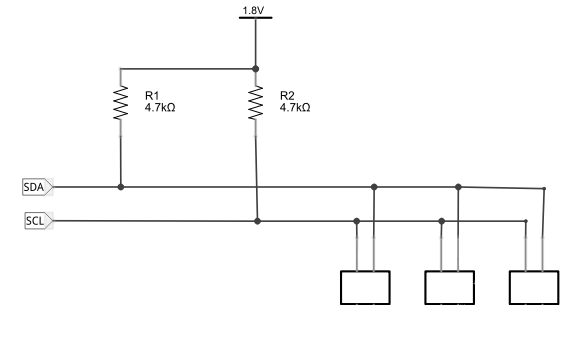
You simply connect the SDA and SCL pins of each of the devices to the pull up resistors. Of course if any of the devices have built-in pullup resistors you can omit the external resistors. More of a problem is if multiple devices each have pull ups. In this case you need to disable all but one set.
The I2C bus is an open collector bus.
This means that it is actively pulled down by a transistor set to on. When the transistor is off, however, the bus returns to the high voltage state via the pullup resistor. The advantage of this approach is that multiple devices can pull the bus low at the same time. That is an open collector bus is low when one or more devices pulls it low and high when none of the devices is active.
The SCL line provides a clock which is used to set the speed of data transfer - one data bit is presented on the SDA line for each pulse on the SCL line. In all cases the master drives the clock line to control how fast bits are transferred. The slave can however hold the clock line low if it needs to slow down the data transfer.
In most cases the I2C bus has a single master device - the Pi in our case - which drives the clock and invites the slaves to receive or transmit data. Multiple masters are possible, but this is advanced and not often necessary.
At this point we could go into the details of how all of this works in terms of bits. However, the library handles these details for us. All you really need to know is that all communication occurs in 8-bit packets.
The master sends a packet, an address frame, which contains the address of the slave it wants to interact with. Every slave has to have a unique address - usually 7 bits but it can be 11 bits and the Pi does support this.
One of the problems in using the I2C bus is that manufacturers often use the same address or same set of selectable addresses and this can make using particular combinations of devices on the same bus difficult or impossible.
The 7-bit address is set as the high order 7 bits in the byte and this can be confusing as an address that is stated as 0x40 in the data sheet results in 0x80 being sent to the device. The low order bit of the address signals a write or a read operation depending on whether it is a zero or a one respectively.
After sending an address frame it then sends or receives data frames back from the slave, There are also special signals used to mark the start and end of an exchange of packets but the library functions take care of these.
This is really all you need to know about I2C in general to get started but it is worth finding out more of the details as you need them - you almost certainly will need them as you debug I2C programs.
The Pi I2C
The processor has three built in I2C masters.
They are referred to as BSC controllers but BSC - Broadcom Serial Controller is essentially an implementation of the I2C bus and you generally don't have to worry about incompatibilities.
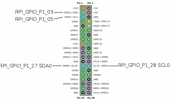
Of the three controllers one, BSC2, is dedicated to working with the HDMI interface. Of the two remaining I2C buses BSC1 is brought out on the main connector at pin 3 GPIO2/SDA1 and pin 5 GPIO3/SCL1 and BSC0 is brought out on pin 27 GPIO0/SDA0 and pin 28 GPIO1/SCL0.
There are 1.6K pull-up resistors on BSC1 and BSC0 is used for expansion card identification and you best not using it. On older versions of the Pi BSC0 was brought out on P5 which wasn't fitted - and is best ignored.
The bcm2835 library only supports BSC1 but it isn't difficult to extend it to support BSC0 if required.
To summarize:
There is one easy to use I2C bus available on pins 3 and 5 complete with 1.6K pullup resistors.
There is an additional I2C bus on pins 27 and 28 but it is allocated to expansion EPROM use and best avoided if possible. There are no pullup resistors fitted.
The bcm2835 only supports the bus on pins 3 and 5.
The hardware can work at 100kHz up to 250MHz and while it supports clock stretching you have to know how to make it work - see later.
The I2C Functions
There are two initialization functions
int bcm2835_i2c_begin (void)

void bcm2835_i2c_end (void)
The begin function changes pins 3 and 5 to ALT0 which gets things ready for I2C data transfer. The end function restores them to default GPIO inputs.
You also have to set the speed of the bus if you don't want to accept the default 100KHz.
There are two functions to set the clock:
void bcm2835_i2c_setClockDivider(uint16_t divider)

void bcm2835_i2c_set_baudrate(uint32_t baudrate)
There are a set of constants to set the clock to common frequencies.
BCM2835_I2C_CLOCK_DIVIDER_2500  10us = 100 kHz

BCM2835_I2C_CLOCK_DIVIDER_626  2.504us = 399.3610 kHz

BCM2835_I2C_CLOCK_DIVIDER_150  60ns = 1.666 MHz (default at reset)

BCM2835_I2C_CLOCK_DIVIDER_148  59ns = 1.689 MHz
Note the frequencies quoted all assume a standard 250MHz clock rate.
The baud rate function is used to mimic the action of the Linux driver's setting. The library doesn't use the Linux driver this is purely for convenience of transferring software. The baud rate is simply the clock speed in Hz.
There is also a function to set the slave devices address for subsequent read/write operations.
void bcm2835_i2c_setSlaveAddress(uint8_t addr)
Simply specify the slaves' address as specified in its data sheet.
Don't worry about any of the low-level descriptions of the way the least significant bit is used to determine if a read or a write is in operation - this is often reported in datasheets as one address for write and one for read. You also need to keep in mind that the 7-bit address is sent as the high order bits in the byte.
For example, a device might report an address of 0x40 on its data sheet. On the bus this would translate to a write address of 0x80 for write and a read address of 0x81 i.e. to write device 0x40 you use 0x80 and to write to it you use 0x81.
However when you specify the devices address you simply use 0x40 and allow the library to convert it as required.
Write
There are two write functions the most basic is:
uint8_t bcm2835_i2c_write(const char * buf, uint32_t len)
This performs a simple write of the buffer to the previously selected slave.
What happens when you use one of these is that first an address frame is transmitted. The address frame is a byte containing the address of the device you specified. Notice that the 7-bit address has to be shifted into the top most bits and the first bit has to be zeroed. So to when you write to a device with an address of 0x40 you would see 0x80 on a logic analyzer i.e. 0x40<<1.
After the address frame as many data frames are sent as you specified in buf and len.
Notice that a multibyte write involves sending a single address frame which means there is a difference between trying to send a block of data one byte at a time, which repeats the address frame and sending it in one go.
If you know about the I2C protocol then it is worth saying that the functions deal with the start sequence, the address frame, it checks the NAK/ACK bit from the slave, sends the data bits, checks the NAK/ACK bit from the slave and sends the stop sequence.
That is in normal use the write transaction sending n bytes is:
START|ADDR|ACK|DATA0|ACK|
       DATA1|ACK|
        ....
          DATAn|ACK|STOP
Notice that it is the slave that sends the ACK bit and if the data is not received correctly it can send NACK instead. Also notice that the Pi only sends a single STOP bit when the entire transaction is complete.
A multibyte transfer is quite different from sending n single bytes one at a time.
 START| ADDR |ACK|DATA0|ACK|STOP
  START| ADDR |ACK|DATA1|ACK|STOP
   ...
   START| ADDR |ACK|DATAn|ACK|STOP
Notice that there are now multiple ADDR frames sent as well as multiple START and STOP bits.
What this means in practice is that you have to look at a device's data sheet and send however many bytes it needs as a single operation - you cannot send the same number of bytes broken into chunks.
Write To A Register
A very standard interaction between master and slave is writing data to a register. This isn't anything special and as far as the I2C bus is concerned you are simply writing raw data but data sheets and users tend to think in terms of reading and writing internal storage locations i.e. registers in the device.
In fact many devices have lots of internal storage, indeed some I2C devices are nothing but internal storage, e.g.. I2C EPROMs.
In this case a standard transaction to write to a register is:
- send address frame
- send a data frame with the command to select the register
- send a data frame containing the byte or word to be written to the register.
So for example you might use:
char buf[]={registerAddress,data};
bcm2835_i2c_write(buf,2);
Notice the command that has to be sent depends on the device and you have to look it up in its datasheet. Also notice that there is a single START and STOP bit at the beginning and end of the transaction.
Read
There are two read functions and this simplest follows the logic of what the write function does:
uint8_t bcm2835_i2c_read (char *buf, uint32_t len)
START|ADDR|ACK|DATA0|ACK|
       DATA1|ACK|
         ...
        DATAn|NACK|STOP
The master sends the address frame and the slave sends the ACK after the address to acknowledge that it has been received and it is ready to send data. Then the slave sends bytes one at a time and the master sends ACK in response to each byte. Finally master sends a NACK to indicate that the last byte has been read and then a STOP bit. That is the master controls how many bytes are transferred.
As in the case of the write functions a block transfer of n bytes is different from transferring n bytes one at a time.
Read A Register
As for writing to a register reading from a register is a very standard operation but it is slightly more complicated in that you need a write and a read operation.
That is to read a register you need a write operation to send the address of the register to the device and then a read operation to get the data that the device sends as the contents of the register.
So for example to read a register, with address reg, you would use something like:
char buf[]={registerAddress};
bcm2835_i2c_write(buf,1);
bcm2835_i2c_read(buf,1);
If the register sends multiple bytes then you can usually read these one after another without sending an address frame each time as a block transfer.
This write/read combination is so common that there is a second read function designed just for this application but with an extra feature. The read_register_rs function will read any number of bytes from a register specified by its address.
uint8_t bcm2835_i2c_read_register_rs (char *regaddr, char *buf, uint32_t len)
In other words this combines writing the registers address with reading it.
In theory and mostly in practice a register read of this sort can work with a stop-start separating the write and the read operation which is what you get if you use separate write and read function calls:
That is the transfer sequence is:
START| ADDR |ACK|REGADDR|ACK|STOP|
      START| DATA1|ACK|
        START| DATA2|ACK|
           ...
      |DATAn|NACK|STOP
If you look at the end of the write and the start of the read you will see that there is a STOP and START bit between them.
For some devices this is a problem. A STOP bit is a signal that another transaction can start and this might allow another master to take over the bus. To avoid this some devices demand a repeated START bit between the write and the read and no STOP bit.
This is referred to as a repeated start bit transaction.
That is the sequence for a repeated start bit register read is:
START|ADDR |ACK|REGADDR|ACK|
   START|DATA0|ACK|
       DATA1|ACK|
   ...
       |DATAn|NACK|STOP
Notice that there is now one ADDR frame and only one STOP bit.
In theory either form of transaction should work but in practice you will find that some slave devices state that they need a repeated start bit and no stop bits in continued transactions. In this case you need to be careful how you send and receive data.
For example to read a register from a device that requires repeated START bits but no STOP bit you would use:
  char buf[] = {0xE7};
  bcm2835_i2c_setSlaveAddress(0x40);
  bcm2835_i2c_read_register_rs(buf,buf,1);
You can see in the logic analyzer display that there is now just a single START bit between the write and the read.
The read_register_rs function sends a single byte to select the register and then reads back as many bytes as the slave device specifies as a response. What if you need to send more than one byte to the slave? You can of course use use a separate write and read function call but there is a special function which will suppress the STOP bits between the write and read of any number of bytes.
uint8_t bcm2835_i2c_write_read_rs(char * cmds,
                uint32_t cmds_len,
                char * buf,
                uint32_t buf_len
)
This writes cmd_len bytes from buf and then reads buf_len bytes from the slave without putting a STOP bit between the write and read. Of course
bcm2835_i2c_write_read_rs(buf,1,buf,1);
is the same as
bcm2835_i2c_read_register_rs(buf,buf,1);
Not many devices need a repeated START transaction the documentation mentions the MLX90620 IR array but this is hardly a common peripheral.
In practice it usually doesn't make any difference if you send a STOP bit in the middle of a write/read transaction but you need to know about it just in case.
Slow Read
The I2C clock is mostly controlled by the master and this raises the question of how we cope with the speed that a slave can or cannot respond to a request for data.
There are two broad approaches to waiting for data on the I2C bus.
The first is simply to request the data and then perform reads in a polling loop. If the device isn't ready with the data then it sends a data frame with a NACK bit set.
The I2C functions return one of the following codes:
| BCM2835_I2C_REASON_OK |
Success |
| BCM2835_I2C_REASON_ERROR_NACK |
Received a NACK |
| BCM2835_I2C_REASON_ERROR_CLKT |
Received Clock Stretch Timeout |
| BCM2835_I2C_REASON_ERROR_DATA |
Not all data is sent / received |
So all we have to do is test for an ERROR_NACK response.
Of course the polling loop doesn't have to be "tight". The response time is often long enough to do other things and you can use the I2C bus to work with other slave devices while the one you activated gets on with trying to get you the data you requested. All you have to do is to remember to read its data at some later time.
The second way is to allow the slave to hold the clock line low after the master has released it. In most cases the master will simply wait before moving on to the next frame while the clock line is held low.
The I2C bus implements this clock stretching protocol but it This is very simple and it means you don't have to implement a polling loop but also notice that your program is frozen until the slave releases the clock line.
The Pi's implementation of I2C clock stretching has a flaw in that it fails if the clock stretching is very short. However there is also a problem with the Linux driver and with the bcm2835 library that may account for many of the reports that I2C doesn't work with clock stretching. The problem is that there is a clock stretch time out register that isn't much discussed and there isn't a library function to set it. By default it is set to 40 but the units are I2C clock pulses. If you are using a high clock rate then 40 clock pulses can be a very short time period and not long enough for devices such as AtoD converters to complete their task.
To make clock stretching work you have to set the timeout - see how to do this in the example that follows.
Many devices implement both types of slow read protocol and you can use which ever suits your application.
A Real Device
Using an I2C device has two problems - the physical connection between master and slave and second figuring out what the software has to do to make it work. In this chapter we take the principle outlined in the previous one and add the information in the HTU21D/Si7021 data sheet to make a working temperature humidity sensor using the I2C functions.
First the hardware.
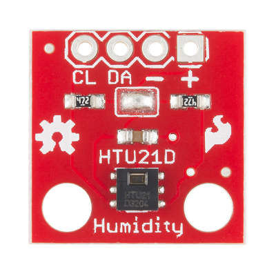
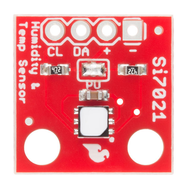
The SparkFun HTU21D/Si7021
The HTU21D Humidity and Temperature sensor or its recent replacement the is one of the easiest of I2C devices to use.
The only problem is that the HTU21D is only available in a surface mount package. To overcome this simply solder some wires onto the pads, it is possible to do, or you can buy a general breakout board.
However, it is much simpler to buy the SparkFun HTU21D/Si7021 breakout board because this has easy connections and built-in pull up resistors. The HTU21D has been replaced by the Si7021 which is more robust than the original and works the same.
https://www.sparkfun.com/products/12064
https://www.sparkfun.com/products/13763
If you decide to work with some other I2C device you can still follow the steps in this account, but you would have to modify what you do to be correct for the device you are using. In particular if you select a device that only works at 5V you might need a level converter.
Wiring the HTU21D
Given that the HTU21D has pull up resistors we really should disable them when used on the internal I2C bus which already has pullups. In practice the additional pullups don't seem to make much difference to the waveforms and you can leave them in place while testing.
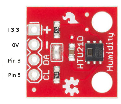
You can use a prototype board to make the connections and this makes it easier to connect other instruments such as a logic analyzer.
A First Program
After wiring up any i2C device the first question that needs to be answered is - does it work?
Unfortunately for most complex devices finding out if it works is a multi-step process.
Our first program will aim to read some data back from the HTU21D - any data will do.
If you look at the data sheet you will find that the device address is 0x40 and its supports the following commands/registers:
| Command | Code | Comment |
| Trigger Temperature Measurement | 0xE3 | Hold master |
| Trigger Humidity Measurement | 0xE5 | Hold master |
| Trigger Temperature Measurement | 0xF3 | No Hold master |
| Trigger Humidity Measurement | 0xF5 | No Hold master |
| Write user register | 0xE6 | |
| Read user register | 0xE7 | |
| Soft Reset | 0xFE |
The easiest of these to get started with is the Read user register command. The user register gives the current setup of the device and can be used to set the resolution of the measurement.
Notice that the codes that you send to the device can often be considered addresses or commands. In this case you can think of sending 0xE7 as a command to read the register or the read address of the register - it makes no difference. In most cases the term command is used when sending the code makes the device do something and and the term address is used when it simply makes the device read or write specific data.
To read the user register we have to write a byte containing 0xE7 and then read the byte the device sends back. Notice that means sending an address frame, a data frame and then another address frame and reading a data frame. The device seems to be happy if you send a stop bit between each transaction or just a new start bit.
A program to read the user register is fairly easy to put together. The address of the device is 0x40 so its write address is 0x80 and its read address is 0x81. As the I2C functions adjust the address as needed we simply use 0x40 as the device's address but it does alter what you expect to see if you example the data being exchanged:
#include <stdio.h>
#include <stdlib.h>
#include <bcm2835.h>
int main(int argc, char** argv) {
if (!bcm2835_init())
        return 1;
 char buf[] = {0xE7};
 bcm2835_i2c_begin ();
 bcm2835_i2c_setSlaveAddress (0x40);
 bcm2835_i2c_write (buf,1);
 bcm2835_i2c_read (buf,1);
 printf("User Register = %X \r\n",buf[0]);
 bcm2835_i2c_end ();
 return (EXIT_SUCCESS);
}
This sends the address frame for 0x80 and then the data byte 0xE7 to select the user register. Next it sends an address frame for 0x81 to read the data.
If you run the program you will see:
Register= 02
this is the default value of the register and it corresponds to a resolution of 12 and 14 bits for the humidity and temperature respectively and a supply voltage greater than 2.25V.
In Detail
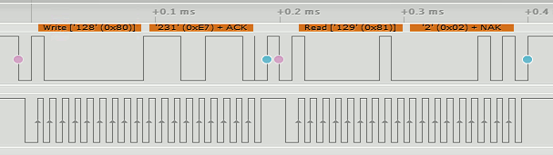
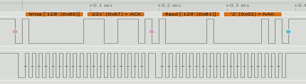
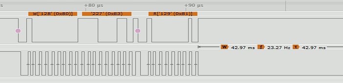
If you have a logic analyzer that can interpret the I2C protocol connected, what you will see is:
You can see that the write_byte function sends an address packet set to the device's 7-bit address 0x40 as the high order bits and the low order bit set to zero to indicate a write i.e 0x80. After this you get a data packet sent containing 0xE7 the address of the register. After a few microseconds it sends the address frame again only this time with the low order bit set to 1 to indicate a read and it then receives back a single byte of data from the device - 0x02.
This all demonstrates that the external device is working properly and we can move on to getting some data of interest.
Reading the raw temperature data
Now we come to reading one of the two quantities that the device measures - temperature.
If you look back at the command table you will see that there are two possible commands for reading the temperature:
| Command | Code | Comment |
| Trigger Temperature Measurement | 0xE3 | Hold master |
| Trigger Temperature Measurement | 0xF3 | No Hold master |
What is the difference between Hold master and No Hold master?
This was discussed earlier in a general context. The device cannot read the temperature instantaneously and the master can either opt to be held waiting for the data, i.e. hold master, or released to do something else and poll for the data until it is ready.
The hold master option works by allowing the device to stretch the clock pulse by holding the line low after the master has released it. In this mode the master will wait until the device releases the line.
Not all masters support this mode but the Pi does and this makes this the simplest option.
To read the temperature using the Hold master mode you simply send 0xE3 and then read three bytes.
bcm2835_i2c_read_register_rs(buf, buf, 3);
uint8_t msb = buf[0];
uint8_t lsb = buf[1];
uint8_t check = buf[2];
printf("msb %d \n\r lsb %d \n\r checksum %d \n\r", msb, lsb, check);
The buffer is unpacked into three variables with more meaningful names - the msb most significant byte, lsb - least significant byte and the check(sum).
If you try this you will find that it doesn't work. The reason is that it almost certainly times out with the default setting of clock stretch time out of 40 clock pulses. At the default clock speed of 1.666MHz this gives a time out of 24 microseconds which is very short. The HTU21D takes something in the region of 40 milliseconds or more to complete a temperature conversion - a timeout is inevitable.
Setting The Clock Stretching Timeout
In most cases when using clock stretching we have to modify the clock stretching timeout. Unfortunately the library doesn't provide a function to do this. It is however fairly easy to create a function to do the job:
void setTimeout(uint16_t timeout) {
 volatile uint32_t* stimeout = bcm2835_bsc1 + BCM2835_BSC_CLKT / 4;
 bcm2835_peri_write(stimeout, timeout);
}
This simply writes to the timeout register using the address constants created by the library.
Now we can make clock stretching work by disabling the timeout by setting a value of zero.
 bcm2835_i2c_begin();
 bcm2835_i2c_setClockDivider(BCM2835_I2C_CLOCK_DIVIDER_150);

 setTimeout(0);
 char buf[4] = {0xE3};
 uint8_t status = bcm2835_i2c_read_register_rs(buf, buf, 3);
 uint8_t msb = buf[0];
 uint8_t lsb = buf[1];
 uint8_t check = buf[2];
 printf("msb %d \n\r lsb %d \n\r checksum %d \n\r", msb, lsb, check);
If you try this out you should find that it works and it prints something like
msb 97
lsb 232
checksum 217
with the temperature in the 20C range.
The logic analyzer reveals what is happening.
First we send the usual address frame and write the 0xE3. Then after a short pause the read address frame is sent and the clock line is held low by the device (lower trace):
The clock line is held low by the device for over 42ms while it gets the data ready. It is released and the three data frames are sent:
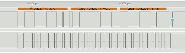
This response really is a long way down the logic analyzers trace so keep scrolling until you find it.
Working with a clock stretch timeout disabled isn't a good idea for a production program but at the default clock rate the longest timeout that can be set using 16 bits is 24.5 milliseconds which is not long enough. To set a timeout of 100 milliseconds the clock has to be at most 1.5 microseconds.
A standard clock rate of BCM2835_I2C_CLOCK_DIVIDER_626 gives a clock time of 2.5 microseconds and a timeout count of 40,000 for 100ms.
The complete program is:
bcm2835_i2c_begin();
bcm2835_i2c_setClockDivider(BCM2835_I2C_CLOCK_DIVIDER_626);

setTimeout(40000);

bcm2835_i2c_setSlaveAddress(0x40);
char buf[4] = {0xE3};
uint8_t status = bcm2835_i2c_read_register_rs(buf, buf, 3);
printf("status=%d\n\r",status);
uint8_t msb = buf[0];
uint8_t lsb = buf[1];
uint8_t check = buf[2];
printf("msb %d \n\r lsb %d \n\r checksum %d \n\r", msb, lsb, check);
This now works reliably and will timeout if anything goes wrong with the slave.
Processing the data
Our next task isn't really directly related to the problem of using the I2C bus but it is a very typical next step. The device returns the data in three bytes but the way that this data relates to the temperature isn't simple.
If you read the data sheet you will discover that the temperature data is the 14-bit value that results by putting together the most and least significant byte and zeroing the bottom two bits. The bottom two bits are used as status bits - bit zero currently isn't used and bit one is a 1 if the data is a humidity measurement and a 0 if it is a temperature measurement.
To put the two bytes together we use:
unsigned int data16=((unsigned int) msb << 8) | (unsigned int) (lsb & 0xFC);
This zeros the bottom two bits, shifts the msb up eight bits and Ors the two together. The result is a 16 bit temperature value with the bottom two bits zeroed.
Now we have raw temperature value but we have still have to convert it to standard units. The datasheet gives the formula
Temp in C = -46.85 + 175.72 * data16 / 216
The only problem in implementing this is working out 216. You can work out 2x with the expression 1<<x i.e. shift 1 x places to the right. This gives:
float temp = (float)(-46.85 + (175.72 * data16 / (float)(1<<16)));
Of course 216 is a constant that works out to 65536 so it is more efficient to write:
float temp = (float)(-46.85 + (175.72 * data16 / (float)65536));
Now all we have to do is print the temperature:
printf("Temperature %f C \n\r", temp);
The final program is:
if (!bcm2835_init())
        return 1;
bcm2835_i2c_begin();
bcm2835_i2c_setClockDivider(BCM2835_I2C_CLOCK_DIVIDER_626);
setTimeout(40000);

bcm2835_i2c_setSlaveAddress(0x40);
char buf[4] = {0xE3};
uint8_t status = bcm2835_i2c_read_register_rs(buf, buf, 3);
printf("status=%d\n\r",status);
uint8_t msb = buf[0];
uint8_t lsb = buf[1];
uint8_t check = buf[2];
printf("msb %d \n\r lsb %d \n\r checksum %d \n\r", msb, lsb, check);

unsigned int data16 = ((unsigned int) msb << 8) | (unsigned int) (lsb & 0xFC);
float temp = (float) (-46.85 + (175.72 * data16 / (float) 65536));
printf("Temperature %f C \n\r", temp);
Reading the humidity
The nice thing about I2C and using a particular I2C device is that it gets easier. Once you have seen how to do it with one device the skill generalizes and once you know how to deal with a particular device other aspects of the device are usually similar.
While clock stretching is the most simple it sometimes doesn't work with some slave and master combinations. It is worth knowing how the alternative polling method works. For this reason let's implement the humidity reading using polling.
Finally we have to find out how to use the No hold master mode of reading the data - it is sometimes useful.
In this case we can't use the read_register_ns command to read and the master because we don't want to keep sending the 0xF5 command. We write it once to the slave and then repeatedly attempt to read the three byte response. If the slave isn't ready it simply replys with a NACK.
   buf[0] = 0xF5;
    bcm2835_i2c_write(buf, 1);
    while (bcm2835_i2c_read(buf, 3) == BCM2835_I2C_REASON_ERROR_NACK) {
        bcm2835_delayMicroseconds(500);
    };
This polls repeatedly until the slave device returns an ACK when the data is loaded into the buffer.
Once we have the data the formula to convert the 16-bit value to percentage humidity is:
RH= -6 + 125 * data16 / 2^16
Putting all this together and reusing some variables from the previous program we have:
 buf[0] = 0xF5;
 bcm2835_i2c_write(buf, 1);
 while (bcm2835_i2c_read(buf, 3) == BCM2835_I2C_REASON_ERROR_NACK) {
        bcm2835_delayMicroseconds(500);
    };
 msb = buf[0];
 lsb = buf[1];
 check = buf[2];
 printf("msb %d \n\r lsb %d \n\r checksum %d \n\r", msb, lsb, check);
 printf("crc = %d\n\r", crcCheck(msb, lsb, check));
 data16 = ((unsigned int) msb << 8) | (unsigned int) (lsb & 0xFC);
 float hum = -6 + (125.0 * (float) data16) / 65536;
 printf("Humidity %f %% \n\r", hum);
 bcm2835_i2c_end();
The only unusual part of the program is using %% to print a single % character - necessary because % means something in printf.
Checksum calculation
Although computing a checksum isn't specific to I2C, it is another common task.
The datasheet explains that the polynomial used is:
X8+X5+X4+1
Once you have this information you can work out the divisor by writing a binary number with a one in each location corresponding to a power of X in the polynomial - i.e. the 8th, 5th, 4th and 1st bit.
Hence the divisor is 0x0131.
What you do next is roughly the same for all CRCs. First you put the data that was used to compute the checksum together with the checksum value as the low order bits:
uint32_t data32 = ((uint32_t)msb << 16)|
                    ((uint32_t) lsb <<8) |
                       (uint32_t) check;
Now you have three bytes, i.e 24 bits in a 32-bit variable.
Next you adjust the divisor so that its most significant non-zero bit aligns with the most significant bit of the three bytes. As this divisor has a one at bit eight it needs to be shifted 15 places to the right to move it to be the 24th bit:
uint32_t divisor = ((uint32_t) 0x0131) <<15;
Now that you have both the data and the divisor aligned, you step through the top-most 16 bits, i.e. you don't process the low order eight bits which is the received checksum. For each bit you check to see if it is a one - if it is you replace the data with the data XOR divisor. In either case you shift the divisor one place to the right:
for (int i = 0 ; i < 16 ; i++){
 if( data32 & (uint32_t)1<<(23 - i) )
                   data32 =data32 ^ divisor;
 divisor=divisor >> 1;
};
When the loop ends, if there was no error, the data32 should be zeroed and the received checksum is correct and as computed on the data received.
A complete function to compute the checksum with some optimizations is:
uint8_t crcCheck(uint8_t msb, uint8_t lsb, uint8_t check){ uint32_t data32 = ((uint32_t)msb << 16)| ((uint32_t) lsb <<8) | (uint32_t) check;uint32_t divisor = 0x988000;for (int i = 0 ; i < 16 ; i++){ if( data32 & (uint32_t)1<<(23 - i) ) data32 ^= divisor; divisor>>= 1; }; return (uint8_t) data32; }
It is rare to get a crc error on an I2C bus unless it is overloaded or subject to a lot of noise.
The Complete Program
The complete program including crc checks is:
#include <stdio.h>
#include <stdlib.h>
#include <bcm2835.h>

uint8_t crcCheck(uint8_t msb, uint8_t lsb, uint8_t check);

int main(int argc, char** argv) {
    if (!bcm2835_init())
        return 1;
    bcm2835_i2c_begin();
    bcm2835_i2c_setClockDivider(BCM2835_I2C_CLOCK_DIVIDER_626);
    setTimeout(40000);
    bcm2835_i2c_setSlaveAddress(0x40);
    char buf[4] = {0xE3};
    uint8_t status = bcm2835_i2c_read_register_rs(buf, buf, 3);
    printf("status=%d\n\r",status);
    uint8_t msb = buf[0];
    uint8_t lsb = buf[1];
    uint8_t check = buf[2];
    printf("msb %d \n\r lsb %d \n\r checksum %d \n\r", msb, lsb, check);
    printf("crc = %d\n\r", crcCheck(msb, lsb, check));
    unsigned int data16 = ((unsigned int) msb << 8) | (unsigned int) (lsb & 0xFC);
    float temp = (float) (-46.85 + (175.72 * data16 / (float) 65536));
    printf("Temperature %f C \n\r", temp);

    buf[0] = 0xF5;
    bcm2835_i2c_write(buf, 1);
    while (bcm2835_i2c_read(buf, 3) == BCM2835_I2C_REASON_ERROR_NACK) {
      bcm2835_delayMicroseconds(500);
    };
    msb = buf[0];
    lsb = buf[1];
    check = buf[2];
    printf("msb %d \n\r lsb %d \n\r checksum %d \n\r", msb, lsb, check);
    printf("crc = %d\n\r", crcCheck(msb, lsb, check));

    data16 = ((unsigned int) msb << 8) | (unsigned int) (lsb & 0xFC);
    float hum = -6 + (125.0 * (float) data16) / 65536;
    printf("Humidity %f %% \n\r", hum);
    bcm2835_i2c_end();
    return (EXIT_SUCCESS);
}

uint8_t crcCheck(uint8_t msb, uint8_t lsb, uint8_t check) {
    uint32_t data32 = ((uint32_t) msb << 16) |
            ((uint32_t) lsb << 8) |
            (uint32_t) check;
    uint32_t divisor = 0x988000;
    int i;
    for (i = 0; i < 16; i++) {
        if (data32 & (uint32_t) 1 << (23 - i))
            data32 ^= divisor;
        divisor >>= 1;
    };
    return (uint8_t) data32;
}

void setTimeout(uint16_t timeout) {
    volatile uint32_t* stimeout = bcm2835_bsc1 + BCM2835_BSC_CLKT / 4;
    bcm2835_peri_write(stimeout, timeout);
}
Of course this is just the start.
Once you have the device working and supplying data it is time to write your code in the form of functions that return the temperature and the humidity and generally make the whole thing more useful and easier to maintain.
This is often how this sort of programming goes - at first you write a lot of inline code so that it works as fast as it can then you move blocks of code to functions to make the program more elegant and easy to maintain checking at each refactoring that the programming still works.
Where Next
Not all devices used standard bus protocols. Next we looks at a custom serial protocol that we have to implement for our selves..
Now On Sale!
You can now buy a print or ebook edition of Raspberry Pi IoT in C from Amazon.
For Errata and Listings Visit: IO Press
This our ebook on using the Raspberry Pi to implement IoT devices using the C programming language. The full contents can be seen below. Notice this is a first draft and a work in progress.
Chapter List
-
Introducing Pi (paper book only)
-
Getting Started With NetBeans In this chapter we look at why C is a good language to work in when you are creating programs for the IoT and how to get started using NetBeans. Of course this is where Hello C World makes an appearance.
-
First Steps With The GPIO
The bcm2835C library is the easiest way to get in touch with the Pi's GPIO lines. In this chapter we take a look at the basic operations involved in using the GPIO lines with an emphasis on output. How fast can you change a GPIO line, how do you generate pulses of a given duration and how can you change multiple lines in sync with each other? -
GPIO The SYSFS Way
There is a Linux-based approach to working with GPIO lines and serial buses that is worth knowing about because it provides an alternative to using the bcm2835 library. Sometimes you need this because you are working in a language for which direct access to memory isn't available. It is also the only way to make interrupts available in a C program. -
Input and Interrupts
There is no doubt that input is more difficult than output. When you need to drive a line high or low you are in command of when it happens but input is in the hands of the outside world. If your program isn't ready to read the input or if it reads it at the wrong time then things just don't work. What is worse is that you have no idea what your program was doing relative to the event you are trying to capture - welcome to the world of input. -
Memory Mapped I/O
The bcm2835 library uses direct memory access to the GPIO and other peripherals. In this chapter we look at how this works. You don't need to know this but if you need to modify the library or access features that the library doesn't expose this is the way to go. -
Near Realtime Linux
You can write real time programs using standard Linux as long as you know how to control scheduling. In fact it turns out to be relatively easy and it enables the Raspberry Pi to do things you might not think it capable of. There are also some surprising differences between the one and quad core Pis that make you think again about real time Linux programming. -
PWM
One way around the problem of getting a fast response from a microcontroller is to move the problem away from the processor. In the case of the Pi's processor there are some builtin devices that can use GPIO lines to implement protocols without the CPU being involved. In this chapter we take a close look at pulse width modulation PWM including, sound, driving LEDs and servos. -
I2C Temperature Measurement
The I2C bus is one of the most useful ways of connecting moderately sophisticated sensors and peripherals to the any processor. The only problem is that it can seem like a nightmare confusion of hardware, low level interaction and high level software. There are few general introductions to the subject because at first sight every I2C device is different, but here we present one. -
A Custom Protocol - The DHT11/22
In this chapter we make use of all of the ideas introduced in earlier chapters to create a raw interface with the low cost DHT11/22 temperature and humidity sensor. It is an exercise in implementing a custom protocol directly in C. -
One Wire Bus Basics
The Raspberry Pi is fast enough to be used to directly interface to 1-Wire bus without the need for drivers. The advantages of programming our own 1-wire bus protocol is that it doesn't depend on the uncertainties of a Linux driver. -
iButtons
If you haven't discovered iButtons then you are going to find of lots of uses for them. At its simples an iButton is an electronic key providing a unique coce stored in its ROM which can be used to unlock or simply record the presence of a particular button. What is good news is that they are easy to interface to a Pi. -
The DS18B20
Using the software developed in previous chapters we show how to connect and use the very popular DS18B20 temperature sensor without the need for external drivers. -
The Multidrop 1-wire bus
Some times it it just easier from the point of view of hardware to connect a set of 1-wire devices to the same GPIO line but this makes the software more complex. Find out how to discover what devices are present on a multi-drop bus and how to select the one you want to work with. -
SPI Bus
The SPI bus can be something of a problem because it doesn't have a well defined standard that every device conforms to. Even so if you only want to work with one specific device it is usually easy to find a configuration that works - as long as you understand what the possibilities are. -
SPI MCP3008/4 AtoD (paper book only)
-
Serial (paper book only)
-
Getting On The Web - After All It Is The IoT (paper book only)
-
WiFi (paper book only)