Writing Bits
Our next task is to implement the sending of some data bits to the device.
The 1-wire bus has a very simple data protocol.
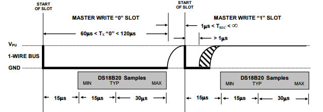
All bits are sent using a minimum of 60 microseconds for a read/write slot. Each slot must be separated from the next by a minimum of 1 microsecond.
The good news is that timing is only critical within each slot. You can send the first bit in a time slot and then take your time before you send the next bit - the device will wait for you. This means you only have to worry about timing within the functions that read and write individual bits.
To send a zero you have to hold the line low for most of the slot.
To send a one you have to hold the line low for just between 1 and 15 microseconds and leave the line high for the rest of the slot.
The exact timings can be seen below;
It seems reasonable to use the typical timing given in the data sheets.
So for a zero we hold the line low for 60 microsecond then let it go high for the remainder of the slot 10 microseconds.
To send a one we hold the line for 6 microsecond and then let it go high for the remainder of the slot 64 microseconds.
As the only time critical operations are the actual setting of the line low and then back to high there is no need to worry too much about speed of operation of the entire function so we might as well combine writing 0 and 1 into a single writeBit function:
void writeBit(uint8_t pin,int b) {
    int delay1, delay2;
    if (b == 1) {
        delay1 = 6;
        delay2 = 64;
    } else {
        delay1 = 80;
        delay2 = 10;
    }
    bcm2835_gpio_fsel(pin, BCM2835_GPIO_FSEL_OUTP);
    bcm2835_gpio_write(pin, LOW);
    bcm2835_delayMicroseconds(delay1);
    bcm2835_gpio_fsel(pin, BCM2835_GPIO_FSEL_INPT);
    bcm2835_delayMicroseconds(delay2);
}
The code at the start of the function simply increases the time between slots slightly. Notice that once again we return the GPIO line to input i.e. high impedance rather than driving the line high at the end of the transaction. This allows the line to be pulled high ready for any response from the slave.
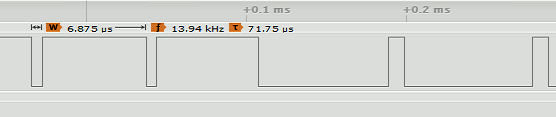
You can see two ones followed by two zeros in the following logic analyzer trace:
A First Command - Writing Bytes
After discovering that there is at least one device connected to the bus the master has to issue a ROM command. In many cases the ROM command used first will be the Search ROM command which enumerates the 64-bit codes of all of the devices on the bus. After collecting all of these codes the master can used the Match ROM commands with a specific 64-bit code to select the device the master wants to talk to.
While it is perfectly possible to implement the Search ROM procedure it is simpler to work with the single device by using commands which ignore the 64-bit code and address all of the devices on the bus at the same time.
Of course this only works as long as there is only one device on the bus.
If there is only one device then we can use the Skip ROM command 0xCC to tell all the devices on the bus to be active.
We now need a function that can send a byte.
As we have a writeBit function this is easy:
void sendskip(uint8_t pin){ writeBit(pin,0); writeBit(pin,0); writeBit(pin,1); writeBit(pin,1);writeBit(pin,0); writeBit(pin,0); writeBit(pin,1); writeBit(pin,1); }
Notice that 0xCC is 1100 1100 in binary and the 1-wire bus sends the least significant bit first.
If you try this out you should find it works but device doesn't respond because it is waiting for another command.
Again as the time between writing bits isn't critical we can take this first implementation of the function and write something more general if slightly slower.
The writeByte function will write the low 8 bits of an int to the device:
void writeByte(uint8_t pin,int byte) {
    int i;
    for (i = 0; i < 8; i++) {
        if (byte & 1) {
            writeBit(pin,1);
        } else {
            writeBit(pin,0);
        }
        byte = byte >> 1;
    }
}
Using this we can send a Skip ROM command using:
writeByte(RPI_GPIO_P1_07,0xCC);
You can see the pattern of bits sent on a logic analyzer: