The SPI bus can be something of a problem because it doesn't have a well defined standard that every device conforms to. Even so if you only want to work with one specific device it is usually easy to find a configuration that works - as long as you understand what the possibilities are.
Now On Sale!
You can now buy a print or ebook edition of Raspberry Pi IoT in C from Amazon.
For Errata and Listings Visit: IO Press
This our ebook on using the Raspberry Pi to implement IoT devices using the C programming language. The full contents can be seen below. Notice this is a first draft and a work in progress.
Chapter List
-
Introducing Pi (paper book only)
-
Getting Started With NetBeans In this chapter we look at why C is a good language to work in when you are creating programs for the IoT and how to get started using NetBeans. Of course this is where Hello C World makes an appearance.
-
First Steps With The GPIO
The bcm2835C library is the easiest way to get in touch with the Pi's GPIO lines. In this chapter we take a look at the basic operations involved in using the GPIO lines with an emphasis on output. How fast can you change a GPIO line, how do you generate pulses of a given duration and how can you change multiple lines in sync with each other? -
GPIO The SYSFS Way
There is a Linux-based approach to working with GPIO lines and serial buses that is worth knowing about because it provides an alternative to using the bcm2835 library. Sometimes you need this because you are working in a language for which direct access to memory isn't available. It is also the only way to make interrupts available in a C program. -
Input and Interrupts
There is no doubt that input is more difficult than output. When you need to drive a line high or low you are in command of when it happens but input is in the hands of the outside world. If your program isn't ready to read the input or if it reads it at the wrong time then things just don't work. What is worse is that you have no idea what your program was doing relative to the event you are trying to capture - welcome to the world of input. -
Memory Mapped I/O
The bcm2835 library uses direct memory access to the GPIO and other peripherals. In this chapter we look at how this works. You don't need to know this but if you need to modify the library or access features that the library doesn't expose this is the way to go. -
Near Realtime Linux
You can write real time programs using standard Linux as long as you know how to control scheduling. In fact it turns out to be relatively easy and it enables the Raspberry Pi to do things you might not think it capable of. There are also some surprising differences between the one and quad core Pis that make you think again about real time Linux programming. -
PWM
One way around the problem of getting a fast response from a microcontroller is to move the problem away from the processor. In the case of the Pi's processor there are some builtin devices that can use GPIO lines to implement protocols without the CPU being involved. In this chapter we take a close look at pulse width modulation PWM including, sound, driving LEDs and servos. -
I2C Temperature Measurement
The I2C bus is one of the most useful ways of connecting moderately sophisticated sensors and peripherals to the any processor. The only problem is that it can seem like a nightmare confusion of hardware, low level interaction and high level software. There are few general introductions to the subject because at first sight every I2C device is different, but here we present one. -
A Custom Protocol - The DHT11/22
In this chapter we make use of all of the ideas introduced in earlier chapters to create a raw interface with the low cost DHT11/22 temperature and humidity sensor. It is an exercise in implementing a custom protocol directly in C. -
One Wire Bus Basics
The Raspberry Pi is fast enough to be used to directly interface to 1-Wire bus without the need for drivers. The advantages of programming our own 1-wire bus protocol is that it doesn't depend on the uncertainties of a Linux driver. -
iButtons
If you haven't discovered iButtons then you are going to find of lots of uses for them. At its simples an iButton is an electronic key providing a unique coce stored in its ROM which can be used to unlock or simply record the presence of a particular button. What is good news is that they are easy to interface to a Pi. -
The DS18B20
Using the software developed in previous chapters we show how to connect and use the very popular DS18B20 temperature sensor without the need for external drivers. -
The Multidrop 1-wire bus
Some times it it just easier from the point of view of hardware to connect a set of 1-wire devices to the same GPIO line but this makes the software more complex. Find out how to discover what devices are present on a multi-drop bus and how to select the one you want to work with. -
SPI Bus
The SPI bus can be something of a problem because it doesn't have a well defined standard that every device conforms to. Even so if you only want to work with one specific device it is usually easy to find a configuration that works - as long as you understand what the possibilities are. -
SPI MCP3008/4 AtoD (paper book only)
-
Serial (paper book only)
-
Getting On The Web - After All It Is The IoT (paper book only)
-
WiFi (paper book only)
SPI Bus Basics
The SPI bus is very strange but commonly encountered as it is used to connect all sorts of devices from LCD displays, through real time clocks and AtoD converters.
It is strange because there is no standard for it and different companies have implemented it in different ways as a result you have to work harder to implement it in any particular case. However it does usually work which is a surprise for a bus with no standard or clear specification.
The reason it can be made to work is that you can specify a range of different operating modes, frequencies and polarities. This makes the bus slightly more complicated to use but generally it is a matter of looking up how the device you are trying to work with implements the SPI bus and then getting the Pi to work in the same way.
The bus is odd in another way - it does not use bidirectional serial connections. There is a data line for the data to go from the master to the slave and a separate data line from the slave back to the master. That is instead of a single data line that changes its transfer direction there is one for data out and one for data in.
It is also worth knowing that the drive on the SPI bus is push-pull and not open collector/drain. This provides higher speed and more noise protection as the bus is driven in both directions.
There is a bidirectional mode where a single wire is used for the data - the Pi doesn't support this.
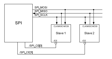
You can see the sort of configuration that the Pi expects. There is a single master and at most two slaves. The signal lines are
- MOSI Master Output Slave Input i.e. data to the slave
- MISO Master Input Slave Output i.e. data to the master
- SCLK Serial Clock which is always generated by the master
There can also be any number of SS - Slave Select - or CE Chip Select - lines which are usually set low to select which slave is being addressed. Notice that unlike other buses I2C for example there are no SPI commands or addresses - only bytes of data. However slave devices do interpret some of the data as commands to do something or send some particular data.
The Pi has only a single SPI bus exposed on the GPIO connector and only two SS lines. This means that in principle you can only connect two SPI devices to the Pi although this is a restriction that is easy to overcome.
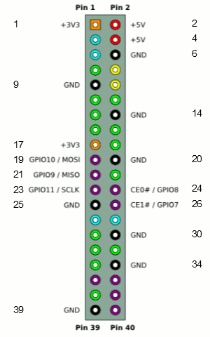
The pins that are used for the Pi's SPI bus are
MOSI   GPIO 10 19  Out
MISO   GPIO 9  21  In
SCLK   GPIO 11 23  Out
CE0    GPIO 8  24  Out
CE1    GPIO 7  26  In
The data transfer on the SPI bus is also slightly odd. What happens is that the master pulls one of the chip selects low which activates a slave. Then the master toggles the clock SCLK and both the master and the slave send a single bit on their respective data lines. After eight clock pulses a byte has been transferred from the master to the slave and from the slave to the master. You can think of this as being implemented as a circular buffer - although it doesn't have to be.
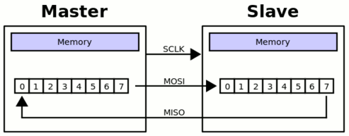
This full duplex data transfer is often hidden by the software and the protocol used. For example there is a read function that reads data from the slave and sends zeros or data that is ignored by the slave. Similarly there is a write function that sends valid data but ignores whatever the slave sends. The transfer is typically in groups of eight bits and usually most significant bit first but this isn't always the case. In general as long as the master supply clock pulses data is transferred.
Notice this circular buffer arrangement allows for slaves to be daisy chained with the output of one going to the input of the next. This makes the entire chain one big circular shift register. This can make it possible to have multiple devices with only a single chip select but it also means any commands sent to the slaves are received by each one in turn. For example you could send a convert command to each AtoD converter in turn and receive back results from each one. (See:https://www.maximintegrated.com/en/app-notes/index.mvp/id/3947)
The final odd thing about the SPI bus is that there are four modes which define the relationship between the data timing and the clock pulse. The clock can be either active high or low - clock polarity CPOL and data can be sampled on the rising or falling edge of the clock - clock phase CPHA. All combinations of these two possibilities gives the four modes:
| SPI Mode | Clock Polarity CPOL |
Clock Edge CPHA |
||
|---|---|---|---|---|
| 0 | 0 | 0 | Clock active high data output on falling edge and sampled on rising | |
| 1 | 0 | 1 | Clock active high data output on rising edge and sampled on falling | |
| 2 | 1 | 0 |
|
|
| 3 | 1 | 1 | Clock active low data output on rising edge and sampled on falling |
The way that the modes are named is common but not universal.
There is often a problem trying to work out what mode a slave device uses. The clock polarity is usually easy and the Clock phase can sometimes be worked out from the data transfer timing diagrams and:
- First clock transition in the middle of a data bit means CPHA=0
- First clock transition at the start of a data bit means CPHA=1
So to configure the SPI bus to work with a particular slave device you have to
- select the clock frequency - anything from 125MHz to 3.8KHz on the Pi.
- set the CS polarity - active high or low
- set the clock mode Mode0 thru Mode3
Now we have to find out how to do this using the bcm2835 library.
The SPI Functions
Initialization
There are two functions concerned with enabling and disabling the SPI bus:
bcm2835_spi_begin ()bcm2835_spi_end ()
Before you make use of the SPI bus you have to initialize it using:
bcm2835_spi_begin ()
This returns 1 is successful and 0 otherwise. After this the pins allocated to the SPI bus no longer work as general purpose GPIO pins. If this function fails the most likely reason is that you are not running the program as root.
When you are finished using the SPI bus you can return the pins to general GPIO lines by calling:
bcm2835_spi_end ()
Configuration
There are a number of functions that you can use to configure the why the bus works.
bcm2835_spi_setClockDivider (uint16_t divider)bcm2835_spi_setBitOrder (uint8_t order)bcm2835_spi_setDataMode (uint8_t mode)bcm2835_spi_chipSelect (uint8_t cs)bcm2835_spi_setChipSelectPolarity (uint8_t cs, uint8_t active)
setClockDivider sets the speed of data transfer as a fraction of the back Pi clock speed. The documentation indicates that only powers of 2 can be used for the divider and there is a predefined enumeration BCM2835_SPI_CLOCK_DIVIDER_powerof2 that you can use. In fact you can use any value for the clock divider. The clock speed is given by
clock speed=250/divider MHz
You can ignore the BitOrder function because it has no effect as the Pi's SPI bus doesn't support it.
setDataMode can be used to set the data transfer to one of:
|
BCM2835_SPI_MODE0 |
CPOL = 0, CPHA = 0 |
|
BCM2835_SPI_MODE1 |
CPOL = 0, CPHA = 1 |
|
BCM2835_SPI_MODE2 |
CPOL = 1, CPHA = 0 |
|
BCM2835_SPI_MODE3 |
CPOL = 1, CPHA = 1 |
ChipSelect sets which chip select line will be involved in all data transfer operations unitl it is changed. You can set any of
|
BCM2835_SPI_CS0 |
Chip Select 0 |
|
BCM2835_SPI_CS1 |
Chip Select 1 |
|
BCM2835_SPI_CS2 |
Chip Select 2 (ie pins CS1 and CS2 are asserted) |
|
BCM2835_SPI_CS_NONE |
No CS, control it yourself |
Finally setChipSelectPolarity can be used to set either of the chip select lines to active high or active low.
In general you should configure the operation of the SPI bus completely but the defaults are:
Mode 0
divider 65536 i.e. aprox 3.81 kHz the slowest clock possible
chip select CS0
chip select polarity active low
Bit order most significant bit first.
Just to make sure that you get the configuration you want you should get in the habit of including:
bcm2835_spi_setBitOrder(BCM2835_SPI_BIT_ORDER_MSBFIRST);
bcm2835_spi_setDataMode(BCM2835_SPI_MODE0);
bcm2835_spi_setClockDivider(BCM2835_SPI_CLOCK_DIVIDER_65536);
bcm2835_spi_chipSelect(BCM2835_SPI_CS0);
bcm2835_spi_setChipSelectPolarity(BCM2835_SPI_CS0, LOW);
This sets the defaults but you can modify the settings as you need.
Data Transfer functions
Because of the way the SPI bus uses a full duplex transfer things are a little different from other buses when it comes to implementing functions to transfer data.
uint8_tbcm2835_spi_transfer (uint8_t value)bcm2835_spi_writenb (char *buf, uint32_t len)bcm2835_spi_transfern (char *buf, uint32_t len)bcm2835_spi_transfernb (char *tbuf, char *rbuf, uint32_t len)
If you recall that the data transfer sends a byte of data out of the register while shifting in a byte of data then the transfer functions will make sense.
The most basic of this set of function is transfer which sends a single byte to the slave while recieving a single byte sent back. Unlike the underlying protocol it doesn't overwrite the original value with the slaves data. So for example to send and recieve data you would use something like:
uint8_t SendData=0x55;
uint8_t ReadData;
Read_data = bcm2835_spi_transfer(Send_data);
Of course you can always simply throw away the data from the slave or send meaningless data to the slave to create something that looks like a read/write pair.
The remaining functions all send multiple bytes of data stored in a buffer. The differ in how they treat the data returned by the slave - writenb ignores it, transfernb stores it in a new buffer and transfern over writes the send buffer with it.
Let's look at each one in turn.
If you just want to write data to the slave and ignore what it sends back then you need to use the writenb function. This takes a char buffer and a length specification and transfers each byte in turn throwing away any data that slave sends back. For example:
char buf[] = {'A','B','C'};
bcm2835_spi_writenb(buf,3);
will send three bytes, containing the ASCII codes for A, B and C, to the slave ignoring any data sent back. Notice that you need to get the size of the buffer correct in the function call to avoid buffer overflow.
The transfern function will send the number of bytes you specify and return the slaves data in the same buffer. For example
char buf[] = {'A','B','C'};
bcm2835_spi_transfern(buf,3);
sends the ASCII codes for A, B C but over writes each element of the array with whatever the slave transfered i.e. buf no longer contains A, B, C.
Finally the transfernb function uses two buffers, one for the data to send and one for the recieved data. For example:
char buf[] = {'A','B','C'};
char readBuf[3];
bcm2835_spi_transfernb(buf,readBuf,3);
sends A,B C to the slave and stores the three bytes sent back into readBuf.
Using just these functions you should be able to deal with most SPI slaves.
Now we come to a subtle point. What is the difference between transfering multiple bytes using transfernb, transfern or writeb and simply sending the bytes individually using multiple transfer calls?
The answer is that each time you make a transfer call the chip select line is activated, the data transfered and then it is deactivated. Using the buffer transfers the chip select is left active for the entire transfer i.e. it isn't deactivated between each byte. Some times this difference isn't important and you can transfer three bytes using three calls to transfer or one call to tranfernb say. Howver some slaves will abort the current multibyte operation if the chip select line is deactivated in the middle of a multibyte transfer.
It is important to realize that the nature of the transfer is that the first byte is sent at the same time that the first byte is recieved. That is unlike other protocols the whole of the send buffer isn't sent before the recieved data comes back. The whole transfer works a byte at a time - first byte is sent while the first byte is being recieved, then the second byte is sent at the same time the second byte is being recieved and so on. Not fully understanding this idea can lead to some interesting bugs.
A Loop Back Example
Because of the way that data is transfered on the SPI bus it is very easy to test that everything is working without out having to add any components. All you have to do is connect MOSI to MISO so that anything send it also received in a loop back mode.
First connect pin 19 to pin 20 using a jumper wire and start a new NetBeans project.
The program is very simple. First we initalize the library and the SPI bus:
if (!bcm2835_init()) {
 return 1;
}
if (!bcm2835_spi_begin()) {
 return 1;
}
If either call fails the chances are you aren't running as root - see chapter 2.
As this is a loop back test we really don't need to configure the bus but for completness:
bcm2835_spi_setBitOrder(BCM2835_SPI_BIT_ORDER_MSBFIRST);
bcm2835_spi_setDataMode(BCM2835_SPI_MODE0);
bcm2835_spi_setClockDivider(BCM2835_SPI_CLOCK_DIVIDER_65536);
bcm2835_spi_chipSelect(BCM2835_SPI_CS0);
bcm2835_spi_setChipSelectPolarity(BCM2835_SPI_CS0, LOW);
Next we can send some data and recieve it right back:
uint8_t read_data = bcm2835_spi_transfer(0xAA);
The hex value AA is useful in testing because it generates the bit sequence 10101010 which is easy to see on a logic analyser
We can check that the recieved data matches the sent data in a variety of ways:
if( read_data== 0xAA) printf("data received correctly");
Finally we close the bus and the library:
bcm2835_spi_end();
bcm2835_close();
return (EXIT_SUCCESS);
Putting all of this together gives us the complete program:
#include <stdio.h>
#include <stdlib.h>
#include <bcm2835.h>

int main(int argc, char** argv) {

 if (!bcm2835_init()) {
  return 1;
 }
 if (!bcm2835_spi_begin()) {
  return 1;
 }

 bcm2835_spi_setBitOrder(BCM2835_SPI_BIT_ORDER_MSBFIRST);
 bcm2835_spi_setDataMode(BCM2835_SPI_MODE0);
 bcm2835_spi_setClockDivider(BCM2835_SPI_CLOCK_DIVIDER_65536);
 bcm2835_spi_chipSelect(BCM2835_SPI_CS0);
 bcm2835_spi_setChipSelectPolarity(BCM2835_SPI_CS0, LOW);

 uint8_t read_data = bcm2835_spi_transfer(0xAA);

 if( read_data== 0xAA) printf("data received correctly");

 bcm2835_spi_end();
 bcm2835_close();
 return (EXIT_SUCCESS);
}
If you run the program and don't get the "data received correctly" message then the most likely reason is that you have connected the wrongt two pins together or not connected them at all.
If you connect a logic analyser to the four pins involved - 19,21, 23 and 24 you will see the data transfer:
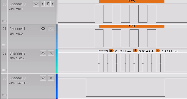
If you look carefully you will see the CS0 line go low before the master places the first data bit on the MOSI and hence on the MISO lines. The documentation states that the CS line is held for at least three core clock cycles before transfer starts and held for at least one clock cycle when the transfer is complete. Notice that the clock rises in the middle of each data bit making this a mode 0 transer. You can also see that the clock is measured to be 3.8KHz as priiomised.
Problems
The SPI bus is often a real headache because of the lack of a definitive standard but in most cases you can make it work. The first problem is in discovering the characteristics of the slave device you want to work with. In general this is solved by a careful reading of the data sheet or perhaps some trial and error - see the next chapter for an example.
If you are working with a single slave then generally things work once you have the SPI bus configuration set correctly. Where things are more difficult is if you have multiple devices on the same bus. The Pi can only directly suport two devices but this is enough to make the task more difficult. Typically you will find SPI devices that don't switch off properly when they are not being addressed. In principle all SPI devices shouldpresent high impedance outputs (i.e. tristate buffers) when not being addressed but some don't. If you encounter a problem you need to check that the selected slave is able to control the MISO line properly.
Another problem, which is particularly bad for the Pi, is noise. If you are using a USB or other power supply to the Pi that isn't able to supply sufficient instantaneous current draw then you will see noise on any or all of the data lines - the CS0/1 lines seem to be particularly sensitive. The solution is to get a better power supply.
If you really need more than two SPI devices then you might be tempted to look at the possiblity of enabling the other SPI buses. This sounds good in theory but in practice it seems to be difficult The documentation advises not to use the SPI bus used for EEPROM I/O in HAT boards in the Pi 2 and later.
A better solution is to multiplex the CS0/1 lines to create additional chip selects. For example you can use standard GPIO lines as chip selects and connect more than two SPI slaves.
Summary
- The SPI bus is often problematic because there is no SPI standard
- Unlike other serial buses it makes use of unidirectional connections.
- The data lines are MOSI master output slave input and MISO master input slave output.
- In addition there is a clock line - output from master and an unspecified number of select lines - two in the case of the Pi.
- Data is transferred from the master to the slave and from the slave to the master on each clock pulse in arranged as a circular buffer.
- The bcm2835 library provides all the functions you need to set up the SPI bus and transfer data one byte or multiple bytes at a time.
- You can test the SPI bus using a simple loopback connection.
- Working with a single slave is usually fairly easy, working with mutliple slaves can be more of a problem.
Now On Sale!
You can now buy a print or ebook edition of Raspberry Pi IoT in C from Amazon.
For Errata and Listings Visit: IO Press
This our ebook on using the Raspberry Pi to implement IoT devices using the C programming language. The full contents can be seen below. Notice this is a first draft and a work in progress.
Chapter List
-
Introducing Pi (paper book only)
-
Getting Started With NetBeans In this chapter we look at why C is a good language to work in when you are creating programs for the IoT and how to get started using NetBeans. Of course this is where Hello C World makes an appearance.
-
First Steps With The GPIO
The bcm2835C library is the easiest way to get in touch with the Pi's GPIO lines. In this chapter we take a look at the basic operations involved in using the GPIO lines with an emphasis on output. How fast can you change a GPIO line, how do you generate pulses of a given duration and how can you change multiple lines in sync with each other? -
GPIO The SYSFS Way
There is a Linux-based approach to working with GPIO lines and serial buses that is worth knowing about because it provides an alternative to using the bcm2835 library. Sometimes you need this because you are working in a language for which direct access to memory isn't available. It is also the only way to make interrupts available in a C program. -
Input and Interrupts
There is no doubt that input is more difficult than output. When you need to drive a line high or low you are in command of when it happens but input is in the hands of the outside world. If your program isn't ready to read the input or if it reads it at the wrong time then things just don't work. What is worse is that you have no idea what your program was doing relative to the event you are trying to capture - welcome to the world of input. -
Memory Mapped I/O
The bcm2835 library uses direct memory access to the GPIO and other peripherals. In this chapter we look at how this works. You don't need to know this but if you need to modify the library or access features that the library doesn't expose this is the way to go. -
Near Realtime Linux
You can write real time programs using standard Linux as long as you know how to control scheduling. In fact it turns out to be relatively easy and it enables the Raspberry Pi to do things you might not think it capable of. There are also some surprising differences between the one and quad core Pis that make you think again about real time Linux programming. -
PWM
One way around the problem of getting a fast response from a microcontroller is to move the problem away from the processor. In the case of the Pi's processor there are some builtin devices that can use GPIO lines to implement protocols without the CPU being involved. In this chapter we take a close look at pulse width modulation PWM including, sound, driving LEDs and servos. -
I2C Temperature Measurement
The I2C bus is one of the most useful ways of connecting moderately sophisticated sensors and peripherals to the any processor. The only problem is that it can seem like a nightmare confusion of hardware, low level interaction and high level software. There are few general introductions to the subject because at first sight every I2C device is different, but here we present one. -
A Custom Protocol - The DHT11/22
In this chapter we make use of all of the ideas introduced in earlier chapters to create a raw interface with the low cost DHT11/22 temperature and humidity sensor. It is an exercise in implementing a custom protocol directly in C. -
One Wire Bus Basics
The Raspberry Pi is fast enough to be used to directly interface to 1-Wire bus without the need for drivers. The advantages of programming our own 1-wire bus protocol is that it doesn't depend on the uncertainties of a Linux driver. -
iButtons
If you haven't discovered iButtons then you are going to find of lots of uses for them. At its simples an iButton is an electronic key providing a unique coce stored in its ROM which can be used to unlock or simply record the presence of a particular button. What is good news is that they are easy to interface to a Pi. -
The DS18B20
Using the software developed in previous chapters we show how to connect and use the very popular DS18B20 temperature sensor without the need for external drivers. -
The Multidrop 1-wire bus
Some times it it just easier from the point of view of hardware to connect a set of 1-wire devices to the same GPIO line but this makes the software more complex. Find out how to discover what devices are present on a multi-drop bus and how to select the one you want to work with. -
SPI Bus
The SPI bus can be something of a problem because it doesn't have a well defined standard that every device conforms to. Even so if you only want to work with one specific device it is usually easy to find a configuration that works - as long as you understand what the possibilities are. -
SPI MCP3008/4 AtoD (paper book only)
-
Serial (paper book only)
-
Getting On The Web - After All It Is The IoT (paper book only)
-
WiFi (paper book only)
Related Articles
Real Raspberry Pi - Getting Started And Custom NOOBS