Electronics is a complicated subject with lots of different types of electronic components. Electronics as it is applied to the IoT or digital electronics in general is in fact a much simpler subject. In particular you can master it with a knowledge of just a small number of devices - the resistor being the number one. In this chapter we look at the basic ways that electricity behaves and how resistors control it.
This is a chapter from our ebook on electronics as applied to the art of digital design or the IoT.
The full contents can be seen below. Notice this is a first draft and a work in progress.
Chapter List
-
Resistance Is (Not) Futile
Electronics is a complicated subject with lots of different types of electronic components. Electronics as it is applied to the IoT or digital electronics in general is in fact a much simpler subject. In particular you can master it with a knowledge of just a small number of devices - the resistor being the number one. In this chapter we look at the basic ways that electricity behaves and how resistors control it.
-
Meet The Sims - Simulating Circuits
Electronics is a physical pursuit in the sense that you have to build circuits to test and use them. However there is a lot to be said for using simulation to try things out. Its much easier and you can check that you have correctly designed a circuit before going to the trouble of building it. The good news is that circuit simulation is a lot easier than you might imagine using open source software.
-
Lowering The Voltage Coming Soon
-
The Transistor BJT
-
The FET
-
Your Workshop - Basic Tools
-
Driving Simple Loads
-
Motors
-
Inputs
-
DAC
-
ADC
-
Logic
Electricity is a mysterious thing - because you can't see it but it definitely does things. You can try to understand it in two distinct ways - using nothing other than math or you can try to gain an intuition in how it behaves. In practice most electronics engineers use both ways to understand it but beginner often have to fall back on the math because they lack any intuition. In fact it is easy to understand many aspects of electricity simply by thinking about things in the real world that we do understand.
In this chapter we look at the simplest behavior of electricity and compare the way it behaves to the way that water flows - the hydraulic model of electricity - and on the way discover how to calculate resistor values to limit its flow.
Voltage And Current
One of the things that confuses the beginner is the way that electrical things are described in terms of voltage and or current.
Why does it take two things to sum up electricity?
Electricity is the flow of electrons, negatively charged particles, in a wire. This is very much like the flow of water or any fluid in a pipe.
If you want to characterize the flow of water in a pipe you might want to state the flow rate - the amount of water per second flowing in the pipe.
This is analogous to electric current which is the flow of charge per second. The unit of electric charge is the Colombo and the unit of electric current is the Amp which is one Coulomb of charge per second. The units may be different but the idea is the same.
What is the second quantity that characterizes the flow of water in a pipe? The answer is pressure. This isn't as familiar a quantity as flow but you do have a basic understanding of it. If you have a wide pipe you can have a lot of water flow at very low pressure - the water flow out of the pipe is very gentle. Alternatively you could have a very narrow pipe and force the same amount of water out of the pipe at high pressure. The flows would be the same but the high pressure hose would knock you over with the violence of its flow.
The equivalent of pressure in a pipe for electricity is Voltage and it is measured in Volts.
The relationship between pressure and flow and voltage and current is a close one. Pressure is what forces the water thought the pipe and voltage drives electricity though wires.
Notice that you can have pressure and voltage without any current flow at all. For example, close the valve on a hose and there is pressure trying to force the water out - but no flow. In the same way you can have a 9V battery with no wires connecting it to anything and so no flow.
So far things are simple but there are many subtle things about electricity that you can understand by thinking carefully about pressure and flow and using this to understand voltage and current.
- Current is flow and measured in Amps
- Voltage is pressure that drives the flow and is measured in Volts.
Voltage Drives Current
If you have a wire then it can vary in how hard it is to get electricity to flow though it. This is the same as having pipes of different diameters - narrow pipes have more resistance to flow than fatter pipes.
So it is with electricity and the how hard it is to force electricity though something is called its resistance and this is measured in Ohms.
The relationship between pressure, resistance and flow is the same for water as it is for electricity and they are governed by a form of Ohm's law. This basically says that if you put a voltage V across a resistance R then the current that flows is given by:
I=V/R
This is reasonable. Double the voltage and you double the flow. Double the resistance and you half the flow.
For example suppose we have a 10V battery and a 1 Ohm resistor what is the current that will flow?
The answer is 10/1 or 10 Amps - which is a lot of current for most electronic circuits.
If you change the resistor to be 1000 Ohms or 1K Ohm then the current is 10/1000 or 1/100 Amp.
Being able to use Ohm's law to work out current is perhaps the most important skill when working with electronics. The reason is simply that most components have a limit on the amount of current they can have flowing though them or can supply. If you arrange things so that they carry or supply more than their maximum then the result is generally blue smoke and a bad smell.
If you want to avoid burned components you need to use Ohm's law to check that the current is low enough.
- Resistance is measured in Ohms
- Ohm's law is I=V/R
- If V is in Volts, R in Ohms then I is in Amp
Circuits
You probably already know that unlike a hose pipe with water electricity always flows in a circle. A better model of what is happening is more like a hose pipe connected to the input and output of a pump. The pump simply circulates the water. In the case of electricity the pump is usually a battery or something that can generate a voltage.
Lets look at a real circuit for a moment.
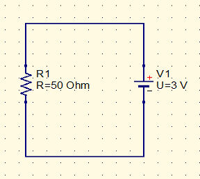
The zig zag is the US symbol for a resistor - Europe uses a rectangle to avoid having to draw the difficult line. The Symbol to the right is a battery. You can see that the resistor is connected across the terminals of the battery. In real life there would be wires and connections and perhaps even some soldering.
This form of diagram, a schematic, only shows you the connections that you have to make. How you make them is up to you. For much electronics a schematic makes the intention of how things are connected clear where say a photo of the real circuit would just look like a mess of wires.
Although many introductory books use drawings of real life and minimize the use of schematics it is important that you learn how to read one - so we will be using them from the word go.
You can think of the battery as a pump that pumps electricity around the circuit. The pump provides 3V of pressure and the resistor in the circuit provides 50 Ohms of resistance.
Notice that in a real circuit the wires used to connect the resistor would themselves have resistance but in practice this is so small that we ignore it and concentrate only on the resistance in the components we use in the circuit.
Now you should have no problem in calculating the current flowing in the resistor.
I=V/R=3/50=0.06 A
or 60mA.
Working With Units
In practice the Ohm is too small a unit for everyday use and the Amp is too big. On the other hand the Volt is about right. What this means is that a 1 Ohm resistor is a very small resistance and not often used. A 1 Amp current on the other hand is fairly large and not often encountered in digital circuits. On the other hand we tend to work with 9 Volt batteries and digital circuits work at anything from 3.3V to 5V.
in practice we tend to work with resistance in at least 1000s of Ohms and so the Kilo Ohm or KOhm i.e. 1000 Ohms is more commonly encountered.
If you connect a resistance in KOhms to a small number of volts then the current that flows is in the 1/1000ths of an Amp or a milli-Amp.
You will also encounter Mega Ohms - 1000,000 Ohms or 1000KOhms and micro-Amps 1/1000,000 Amp or 1/1000 of a milli-amp.
Again these two units tend to go together because it you put a few volts across a resistance in the Mega-Ohm range you tend to get currents in the micro-Amp range.
Units:
1mA or 1 milli-Amp is 1/1000th of an amp. To convert Amps to milli-Amps multiply by 1000.
1uA or 1 micro-Amp is 1/1000,000 of an amp or
1/100th of a milli-Amp. To convert milli-Amps to micro-Amps multiply by 1000

1KOhm is 1000 Ohms
1MOhm is 1000 KOhms or 1000,000 Ohms.
If you use Ohm's law with resistance in KOhms then the current will be in mA. For example 9V applied across 20KOhms gives a current of:
9/20=0.45 mA
Similarly if you use Ohm's law with resistances in MOhms the current will be in micro-Amps. For example 9V applied across 20MOhms gives a current of:
9/20=0.45 uA
Resistance Is Not Futile
Electronics as applied to digital devices has a different emphasis to general electronics. One of the big differences is that you can mostly get away with just knowing about resistors and Ohm's law. You do need to know a little about some other devices like transistors, FETs, LEDs and so on but really it is the resistor that gives you most of your problems.
You will find that the only calculations you have to do are in selecting the correct resistor to set the current following or as we shall see to reduce a voltage.
In short - you are going to be using resistors as one of your basic building blocks.
Before moving on we need to discover a little about real world resistors.
A resistor is a fairly simple device. They are made in many different ways but you can more or less ignore what a resistor is made from in most digital applications. They also come in a number of different shapes and sizes but the one you will most often use is the common "through hole" or wire ended resistor:
If you start to build advanced devices then you will also encounter surface mount resistors but in this introductory book we will ignore this form of packaging.
A resistor differs in its resistance, its accuracy and its power handling capacity.
Obviously you need a resistor to be close to the resistance value you have calculated but resistors are not made with 100% accuracy. Typically a resistor will be within 20%, 10%, 5% and so on. Obviously the cost of a resistor depends on how accurate it is.For most digital applications a 5% tolerance is more than good enough.
Next we come to the topic of preferred values.
You can't ask for a resistor of any value you care to calculate. There is no resistor with a resistance of 314.159 Ohms. The reason is obvious in that you would need to manufacture an infinite set of resistors to satisfy every need. It also isn't necessary because if your resistors are only 10% accurate your 314.159 Ohm could be as big as 345 Ohm or as small as 283 Ohm.
What manufacturers do is to create a series of values that covers the possible range taking account of the tolerance. For example the E6 series has the values
10 15 22 33 47 68
and this covers the range 0 to 100 in 20% intervals. If you are working with 20% resistors you calculate the value you want 314.159 Ohms and then select the closest E6 series value - 330 Ohms in this case.
For a typical 5% resistor used in digital design the preferred values are taken from the E24 series:
10  12  15  18  22  27  33  39  47  56  68  82
11  13  16  20  24  30  36  43  51  62  75  91
And in this case the closest resistor to 314.159 Ohms is 300 Ohms.
Don't become obsessed by the need to get a resistor that is exactly what you calculate. Electronic components are tolerant of small changes and the E24 series is usually more than enough resistors.
Power handling capacity of a resistor simply sets the amount of current that a resistor can take without bursting into flames. When electricity flows things heat up. The amount of power a resistor can dissipate is given in Watts and you can find the number of Watts a resistor has to dissipate using the formula:
P=I2R
For example the resistor in our previous circuit has a current of
I=0.6 A
and a resistance of 50 Ohms so it is dissipating
(0.6)2 * 50 W
or 18 Watts - which for a digital circuit is a lot of power.
Typical resistors used in digital electronics are never called on to work with more than 0.25W - the reason is that you generally want to design your circuits to consume as little power as possible.
However it is worth keeping in mind that if you do design something that runs a large motor a heater or a bright light source any resistors used could be called on to carry more than the typical 0.25W resistor. You may need to buy something special!
Finally - how do you determine the resistance of a particular resistor?
The answer is the infamous color code.
Being able to read a color code is a mark that you are an electronics engineer. However today you can get by with a good multimeter that will measure the resistance of the device in front of you.
The only thing you need to learn is the following table:
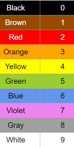
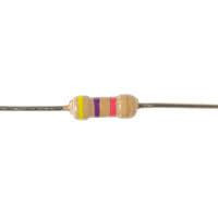
You use this code to read the value of a resistor in a fairly obvious way. The first two colored bands give you the first two significant digits of the value and the third gives its magnitude. For example the resistor shown below;
has a yellow and an violet first and second band so its value is 47. The third band is red which is 2 and so the magnitude is 102 or a 100. So the value of the resistor is 47*100 or 4700 or 4.7K Ohms.
There are lots of resistor color code decoders on the web and if you are short of a project it doesn't take long to implement one.
The only problem that you might have is working out which end to start reading the colors from. There is usually a bigger gap and the end of the colored bands. Alternatively you can look out for the gold or silver 1% or 5% tolerance indicators.
In the last resort if you are uncertain about the value of a resistor you can always measure its resistance with a multi-meter.
Calculating An LED Resistor
With just the few ideas introduced in this chapter, and one small extra, you can already do something useful and something you couldn't before - calculate the resistor needed to keep an LED safe.
An LED - Light Emitting Diode - is one of the basic output devices you will use in building IoT devices. In principle all you have to do is place a voltage across the diode the correct way around and it will light up.
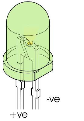
You can identify the polarity of an LED usually from the flat edge.
An LED is a strange device compared to a resistor. It is the first example of a non-Ohmic device. Ohmic devices like resistors are very simple - the current through them is proportional to the voltage across them, double the voltage and you double the current. This isn't true for a non-Ohmic device.
For example an red LED has a voltage of about 1.8 to 2.2V across it almost no matter what current is flowing. This is called its forward voltage and yes increasing it does increase the current though the LED but not by much. For practical purposes you can treat the red LED as if it has 1.8 to 2.2V across it independent of the current. The forward voltage is different for different colors of LED.
If you try to imagine what this sort of behavior would be in terms of water flow then you would probably have to invent something very complicated. Roughly speaking the behavior or an LED would correspond to some sort of water valve that automatically adjusted the flow to always have the same pressure across it. That is if you try to increase the pressure across the valve it will just open more to allow more water to flow to relieve the pressure.
So it is with the LED. If you try to increase the voltage across an LED it will allow more current to flow in an effort to reduce the voltage.
As well as having a forward voltage specification LED's also have a peak forward current. If you put more current though the LED than this the result is fried LED. For red LED's the forward current is in the range 20-30mA.
If you don't know the exact values for a red LED, because you just found it in a box of mixed components say, then assume that it has a forward voltage of 1.8V and a forward current of 20mA and then you almost certainly will not destroy it.
First let's find out how not to connect and LED.
In the diagram below we have a 5V batter connected to an LED.
The question is what is the current in the LED?
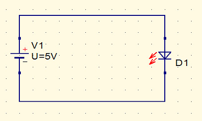
If you think about the water flow model for a moment you will realize exactly what is going to happen here. If you recall our earlier statement:
If you try to increase the voltage across an LED it will allow more current to flow in an effort to reduce the voltage.
In this case the battery is trying to put 5V across the LED so the LED "opens up" and tries to let a lot of electricity though so reducing the voltage. With a theoretical battery the LED would have to allow an infinite current before it saw any effect on the battery voltage. With a real battery the current is limited to however much the battery can supply - if this is more than about 20mA the LED will fail.
This is not a good way to run an LED.
The simplest solution is to include a resistor that will limit the current to 20mA.
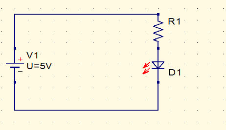
The question what value of resistor do you need? To get the answer you have to add one more idea to what you already know. The LED is going to have about 1.8V across it no matter what current is flowing though it.
So what voltage does the resistor have across it?
The answer is 5 - 1.8 = 4.2V.
For components connected in series in this way the voltage is divided up between them. This is an idea we return to later.
Now that you know the voltage across the resistor you can work out what value you need to set the current to 20mA. Notice that the current that goes through the resistor has to be the current that does though the LED - it has no where else to go!
Using Ohm's law we have:
R=V/I= 4.2/20= 0.21K Ohms
So now we know we need a 210 Ohm resistor. Of course there is no such thing as a 210 Ohm resistor and the nearest bigger resistor in the E24 series is 240 Ohm. We chose the bigger value because this reduces the current rather than pushing it over the 20mA limit.
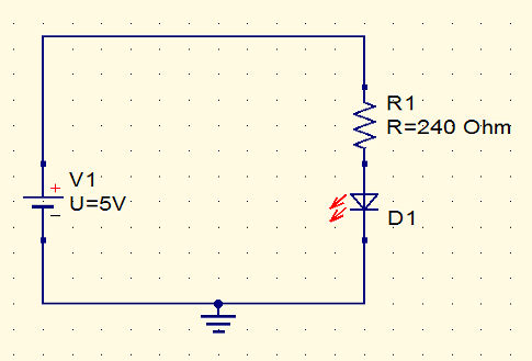
If you build the circuit - or simulate it, see the next chapter - then you will find that rather than 20mA you will probably get something like 14mA but we are erring on the side of safely. The reason for the lower current is that the LED forward voltage is likely to be higher than 1.8V.
If you follow the calculation you will see that in general the resistor that you need is given by:
R=(VSS-VF)/IF
Where VSS is the supply voltage, VF the forward voltage and IF the forward current.
Now you can apply the formula and you know why it works.
Exercise
Just to check that you have the idea about current limiting resistors and voltage try the following design problem.
The question is a difficult one and it is often solved in completely wrong ways so if you get close you have done well.
Suppose you want to drive two red LEDs in series as shown in the diagram
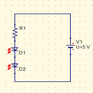
The question is what is the value of R1 needed to limit the current in the LEDs to 20mA?
You can assume that the forward voltage of both LEDs is 1.8V.
Answer:
As the voltage across each LED is 1.8V the total voltage across both is 3.6V. The is more to say about how voltage distributes itself across components in series in chapter 3 but this is just like the way the voltage shared itself across the resistor and the LED in the first example.
So if there is. 3.6V across the two LEDs there is only 5-3.6=1.4 across the resistor so to set the current in the resistor to 20mA we need:
R=V/I=1.4/20=0.07 KOhms=70 Ohms.
The closest E24 resistor is 75 Ohms and this makes the predicted current
I=V/R=1.4/75=0.186 or 19mA.
In practice the current is likely to be lower and you can use anything from 50 to 75 Ohms.
This is a chapter from our ebook on electronics as applied to the art of digital design or the IoT.
The full contents can be seen below. Notice this is a first draft and a work in progress.
Chapter List
-
Resistance Is (Not) Futile
Electronics is a complicated subject with lots of different types of electronic components. Electronics as it is applied to the IoT or digital electronics in general is in fact a much simpler subject. In particular you can master it with a knowledge of just a small number of devices - the resistor being the number one. In this chapter we look at the basic ways that electricity behaves and how resistors control it.
-
Meet The Sims - Simulating Circuits
Electronics is a physical pursuit in the sense that you have to build circuits to test and use them. However there is a lot to be said for using simulation to try things out. Its much easier and you can check that you have correctly designed a circuit before going to the trouble of building it. The good news is that circuit simulation is a lot easier than you might imagine using open source software.
-
Lowering The Voltage Coming Soon
-
The Transistor BJT
-
The FET
-
Your Workshop - Basic Tools
-
Driving Simple Loads
-
Motors
-
Inputs
-
DAC
-
ADC
-
Logic