Controlling a Servo
Hobby servos, the sort used in radio control models, are very cheap and easy to use and the Pi has enough PWM lines to control two of them without much in the way of extras.
A basic servo has just three connections - usually ground and power line and a signal line. The colors used vary but the power is usually red and the ground line is usually black or brown. The signal line is white, yellow or orange.
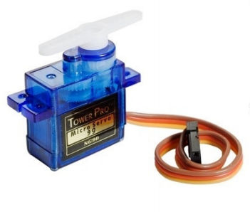
The power wire has to be connected to 5V supply capable of providing enough current to run the motor - anything up to 500mA or more depending on the servo. In general you cannot power a full size servo from the Pi's 5V pin, you need a separate power supply. You can power some micro servos directly from the Pi's 5V line but you need to check the specifications.
The good news is that the servo signal line generally needs very little current, although it does need to be switched between 0 and 5V using a PWM signal.
You can assume that the signal line needs to be driven as a voltage load and so the appropriate way to drive the servo is:
The servo's + line needs to be connected to an external 5V power supply unless it is a micro servo when it might be possible to power it from the Pi's 5V line.
The 10K resistor R1 can be a lot larger for most servos - 47K often works. The 5.6K resistor limits the base current to slightly less than 0.5mA.
Now all we have to do is set the PWM line to produce 20ms pulses with pulse widths ranging from 0.5 to 2.5 ms.
As described earlier the best way to work out a configuration that gives a particular repeat rate is to start at the highest clock rate and work out the range needed.
For example, with a clock of 9.6MHz the range needed to give a 20ms repeat rate is:
max range=repeat time*clock frequency
= 192000
This gives you the maximum range you can use. If you actually want a smaller range you can reduce the clock to a lower frequency and the divider you need is:
divider =2* max range/desired range
The two is because the smallest divider you can use is 2.
So to get a range of 1024 i.e. a 16 bit resolution we need a clock divider of:
divider=2*192000/1024= 375
If you use a divider of 375 and a range of 1024 you will find that the repetition rate is, as promised, 20ms.
Most servos work on a pulse width ranging from 500 microseconds to 2.5 milliseconds or a duty cycle of 2.5% to 12.5% but this varies quite a lot according to the servo.
Using a range of 1024 this corresponds to a range of data from 25 to 128.
So the simplest servo program you can write is something like:
if (!bcm2835_init())
        return 1;

    bcm2835_gpio_fsel(18, BCM2835_GPIO_FSEL_ALT5);
    bcm2835_pwm_set_clock(375);
    bcm2835_pwm_set_mode(0, 1, 1);
    bcm2835_pwm_set_range(0, 1024);

    for(;;){
     bcm2835_pwm_set_data(0,25);
     bcm2835_delayMicroseconds(2000000);
      bcm2835_pwm_set_data(0, 50);
      bcm2835_delayMicroseconds(2000000);
      bcm2835_pwm_set_data(0, 128);
      bcm2835_delayMicroseconds(2000000);
    }
This moves the servo to three positions and pauses between each. If you run the program using the circuit given earlier you will discover that the servo does nothing at all - apart perhaps from vibrating.
The reason is that the transistor voltage driver is an inverter. When the PWM line is high the transistor is fully on and the servo's pulse line is effectively grounded. When the PWM line is low the transistor is fully off and the servo's pulse line is pulled high by the resistor.
A common solution to this problem is to drive the servo using an emitter follower configuration, but in this case this isn't possible because the maximum voltage an emitter follower configuration would generate is 3.3-0.6=2.7V, which is too low to drive most servos.
The standard solution in this case is to use two transistors to generate a non-inverted pulse but it is possible to use a single transistor in a non-inverting configuration.
The simplest solution of all is to ignore the problem in hardware and solve the problem in software.
This is generally good advice. Before you consider modifying the hardware always see if there is an easier software fix.
Instead of generating 20ms pulses with pulse widths 0.5 to 2.5ms, you can generate an inverted pulse with 20ms pulses with widths in the range 17.5 to 19 ms. The principle is that if the servo needs a 10% duty cycle we supply it with a 90% duty cycle which the inverter converts back to a 10% duty cycle.
The range of duty cycles we need goes from 17.5 to 19.5.ms which in percentages is 87.5% to 97.5% or as values 895 to 997.
Simple math can convert an angle T to a value in the range 895 to 997:
value = (997-895)/180*T+895
= 138*T/180+895
To make sure this works with all servos it is a good to restrict the range to 1ms to 2ms or inverted 18ms to 19ms and hence values from 920 to 972
value=52*T/190+920
So we can write the same testing program as:
  if (!bcm2835_init())
        return 1;
    bcm2835_gpio_fsel(18, BCM2835_GPIO_FSEL_ALT5);
    bcm2835_pwm_set_clock(375);
    bcm2835_pwm_set_mode(0, 1, 1);
    bcm2835_pwm_set_range(0, 1024);

    for(;;){
     bcm2835_pwm_set_data(0,52 * 0 / 180 + 920);
     bcm2835_delayMicroseconds(2000000);
      bcm2835_pwm_set_data(0, 52 * 90 / 180 + 920);
      bcm2835_delayMicroseconds(2000000);
      bcm2835_pwm_set_data(0, 52 * 180/ 180 + 920);
      bcm2835_delayMicroseconds(2000000);
    }
If you run this program you should find that the servo moves as promised - however it might not reach its limits of movement.
Servos differ in how they respond to the input signal and you might need to calibrate the pulse widths. Many robot implementations, for example, calibrate the servos to find their maximum movement using either mechanical switches to detect when the servo is at the end of its range or a vision sensor.
You can see from the logic analyzer plot that the PWM pulse train at the GPIO pin is "inverted" as desired.