How Fast Can You Modulate?
Of course in most cases the whole point is to vary the duty cycle or the period of the pulse train for reasons that will be discussed later. This means that the next question is how fast can you change the characteristic of a PWM line?
In other words how fast can you change the duty cycle say?
There is no easy way to give an exact answer and in most applications an exact answer isn't of much value. The reason is that for a PWM signal to convey information it generally has to deliver a number of complete cycles with a given duty cycle. This is because of the way pulses are often averaged in applications.
We also have another problem - synchronization.
There is no way to swap from one duty cycle to another exactly when a complete duty cycle has just finished. What this means is that there is going to be a glitch when you switch from one duty cycle to another. Of course this glitch becomes less important as you slow the rate of duty cycle change and exactly what is useable depends on the application.
For example if you try changing the duty cycle about every 200 microseconds and the repeat is 25 microseconds then you are going to see roughly three to four pulses per duty cycle:
   bcm2835_gpio_fsel(18, BCM2835_GPIO_FSEL_ALT5);
   bcm2835_pwm_set_clock(2);
   bcm2835_pwm_set_mode(0, 1, 1);
   bcm2835_pwm_set_range(0, 256);
   for (;;) {
        bcm2835_pwm_set_data(0, 10);
        bcm2835_delayMicroseconds(10);
        bcm2835_pwm_set_data(0, 200);
        bcm2835_delayMicroseconds(10);
    }
This results in a fairly irregular pulse pattern:

Notice that now we are using an 8 bit duty cycle resolution and setting the duty cycle from 10/256 to 200/256.
The timing of the change and the time it takes to make the change cause the glitches between duty cycles so sometimes we get two and sometimes just one cycle of each duty cycle.
The point is that there is time lost in changing the duty cycle and you simply cannot use PWM with modulation that involves just a few cycles.
If you change and generate duty cycle changes every 500 microseconds or so then the pattern looks a lot better because you are going to see 19 to 20 pulses before each change.

What all this is really about is trying to lower you expectation of how sophisticated you can be in using PWM.
The fastest PWM repetition rate that you can use is about 25 microseconds for an 8 bit resolution and to minimize the glitches you need to leave the duty cycle stable for 10 to 20 pulses i.e. about 200-600 microseconds.
In many applications this is very acceptable but don't expect to use PWM to send coded data and using it for waveform synthesis as a DtoA converter is limited to around 4KHz.
Uses of PWM - DtoA
What sorts of things do you use PWM for?
There are lots of very clever uses for PWM. However there are two use cases which account for most PWM applications - voltage or power modulation and signaling to servos.
The amount of power delivered to a device by a pulse train is proportional to the duty cycle. A pulse train that has a 50% duty cycle is delivering current to the load only 50% of the time and this is irrespective of the pulse repetition rate.
So duty cycle controls the power but the period still matters in many situations because you want to avoid any flashing or other effects - a higher frequency smoothes out the power flow at any duty cycle.
If you add a low pass filter to the output of a PWM signal then what you get is a voltage that is proportional to the duty cycle. This can be looked at in many different ways but it is again the result of the amount of power delivered by a PWM signal. You can also think of it as using the filter to remove the high frequency components of the signal leaving only the slower components due to the modulation of the duty cycle.
How fast you can work depends on the duty cycle resolution you select. If you work with 8 bit resolution your DtoA will have 256 steps which at 3.3V gives a potential resolution of 3.3/256 or about 13mV. This is often good enough. At the fastest clock rate this gives a repetition rate of 37.5KHz which sounds as if it should be enough for audio synthesis.
The PWM output in this configuration mimics the workings of an eight bit AtoD converter. You set the duty cycle using the data value 0 to 256 and you get a voltage output that is 3.3*data/256V.
The repetition rate is around 25 microseconds and the usual rule of thumb is that you need ten pulses to occur per conversion i.e. the maximum frequency you can produce is pulse rate/10.
This means that the fastest signal you can create about 3KHz - which isn't fast enough for a great many applications and you can't use it for sound synthesis in particular.
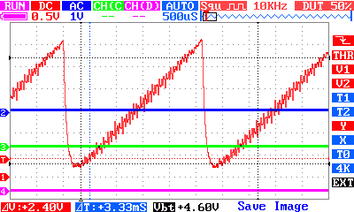
To demonstrate the sort of approach that you can use to DtoA conversion the following program creates a triangle or ramp waveform. :
   for (;;) {
        for (i = 0; i < 256; i = i + 10) {
            bcm2835_pwm_set_data(0, i);
            bcm2835_delayMicroseconds(100);
        }

    }
The inner for loop sets a value of 0 to 256 in steps of 10 i.e. 300mV per step and the delay of 100 microseconds produces an total loop time of over 106 microseconds and this means that around three or four pulses of each 25 microsecond duty cycle should be produced - which is far to few but it is interesting to see what happens. The waveform repeats after around 2.5 ms which makes the frequency around 400Hz. The measured repeat, using an oscilloscope, time is more like 2.3ms or 430Hz.
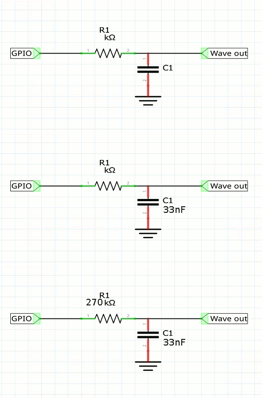
To see the analog wave form we need to put the digital output into a low pass filter. A simple resistor and capacitor work reasonably well:
 The filter's cut off is 17KHz and might be a little on the high side for this low frequency output.

You can create a sine wave or any other waveform you need using the same techniques but 400-800Hz is a practical upper limit on what you can manage.
If you already know that the PWM outputs are used to create audio on the Pi you might be wondering how this is possible with a 800Hz upper limit? The answer is that there are other clock sources, up to 500MHz that can be use to drive the PWM lines.
If you change to mode 0 i.e. balanced output the oscilloscope trace looks little different but there is a lot more spurious RF inference generated.
Music?
So how can the Pi generate musical notes?
The simplest solution is not to try to generate anything other than a square wave. That is use the pulse period rather than duty cycle.
As the frequency of middle C is 281.6Hz the period using a clock rate of 9.6Mhz you would have to set range to 34091 to get the correct frequency.
range= clock frequency/target frequency=34091
So to generate middle C you could use:
    bcm2835_gpio_fsel(18, BCM2835_GPIO_FSEL_ALT5);
    bcm2835_gpio_fsel(13, BCM2835_GPIO_FSEL_ALT0);
    bcm2835_pwm_set_clock(2);
    bcm2835_pwm_set_mode(0, 1, 1);
    int C=34091;
    bcm2835_pwm_set_range(0, C);
    bcm2835_pwm_set_data(0, C/2);
The resulting output is a square wave with a measured frequency of 281.5Hz which isn't particularly nice to listen to. You can improve it by feeding it though a simple low pass filter like the one in used for waveform synthesis.
You can lookup the frequencies for other notes and use a table to generate them.
