Simulating the LED Resistor
As an example of something slightly more useful we close this chapter with the simulation of the LED current limiting resistor as introduced in chapter 1.
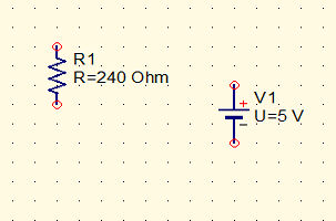
Start a new project and place a resistor (vertical) and a DC voltage source on the diagram. Right click on the DC source and set its voltage to 5V. Repeat for the resistor and set its value to 240 Ohms.
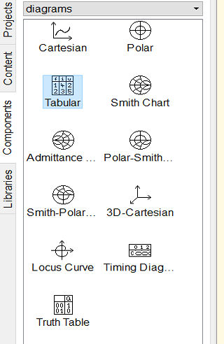
Next we need an LED. You wont find this in the components tab because LEDs vary in their characteristics so they are put together with a range of real components in the Libraries tab:
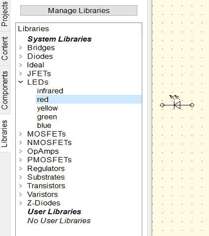
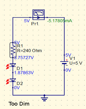
Place red LED into the diagram (right click to make it vertical) and then wire it up as shown:
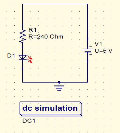

You also need to add a ground symbol and a DC Simulation block. Save the design and use the Calculate DC bias command or F8 key.
The result is:
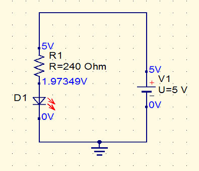
You can see that with a 240 Ohm resistor the LED's forward voltage is 1.97V which is higher than we assumed in the calculation.
Full Simulation
The real question is what is the current?
We could put a current probe into the circuit but there is an easier and more general way to find out. If you run a general simulation F2 rather than a DC bias calculation you will discover that you are taken to look at a new blank tab. This is where you can examine the full results of the simulation.
The palette to the left is now showing a range of plots that you can create to illustrate the results. In our case the simulation is so simple and we don't have any time varying data so the only sensible thing to do is display the static values in a table.
Place a table - corresponding to the icon Tabular - onto the page. A dialog box appears:
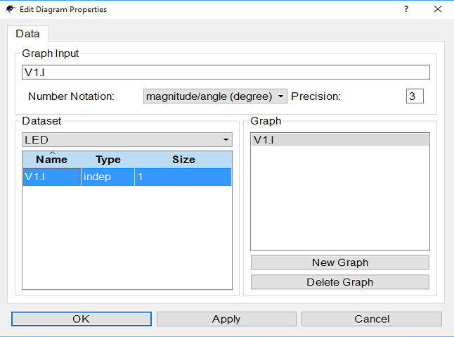
If you look at the Dataset box you will see that there is a single variable V1.I. In general you will find variables like name.I and name.V which correspond to the voltage and current in the named device. In this case we only have the current in V1 the battery. It is possible to add additional variables but more of this later. We only need V1.I because the current in the battery is the current in the resistor and in the LED - where else could the current go. You can select V1.I by double clicking on it when it will appear in the Graph box. Clicking ok places the table on the page:
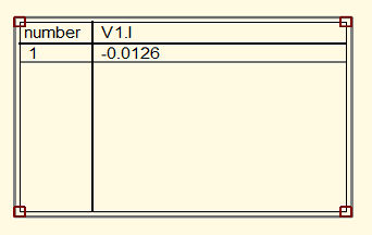
From this you can see that the current is -0.0126A or 12mA which is a bit less than the 20mA we were aiming for. The discrepancy is entirely due to the different forward voltage used by the simulator.
If you want to you can place a table of results on the same page as the schematic diagram so that you can see both at the same time. Simply drag and drop a table onto the same page and then customize it.
You can now play around with varying the load resistor, battery voltage and even LED type to see what happens. In the real world this would take a so much time that you are unlikely to actually do it.
This is the big advantage of using a simulator - you can learn so much in a very short time.
Exercise
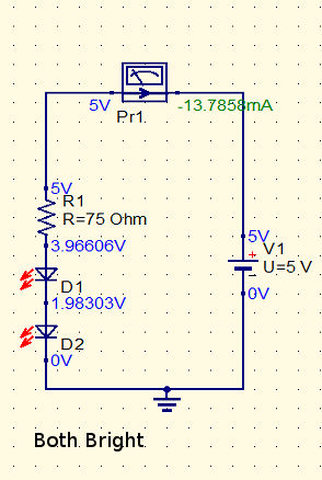
Simulate the two LED circuit given at the end of chapter 1 but don't change the 240 Ohm resistor in the one LED circuit above.
What is the current through the LEDs?
Will the LEDs be bright?
What is the current if you change to a 75 Ohm resistor?
Will the LEDs be bright?
Rollover For Answers
This is a chapter from our ebook on electronics as applied to the art of digital design or the IoT.
The full contents can be seen below. Notice this is a first draft and a work in progress.
Chapter List
-
Resistance Is (Not) Futile
Electronics is a complicated subject with lots of different types of electronic components. Electronics as it is applied to the IoT or digital electronics in general is in fact a much simpler subject. In particular you can master it with a knowledge of just a small number of devices - the resistor being the number one. In this chapter we look at the basic ways that electricity behaves and how resistors control it.
-
Meet The Sims - Simulating Circuits
Electronics is a physical pursuit in the sense that you have to build circuits to test and use them. However there is a lot to be said for using simulation to try things out. Its much easier and you can check that you have correctly designed a circuit before going to the trouble of building it. The good news is that circuit simulation is a lot easier than you might imagine using open source software.
-
Lowering The Voltage Coming Soon
-
The Transistor BJT
-
The FET
-
Your Workshop - Basic Tools
-
Driving Simple Loads
-
Motors
-
Inputs
-
DAC
-
ADC
-
Logic
- << Prev
- Next