A First Circuit Simulation
All we are going to do is create a circuit with a single resistor connected to a battery.
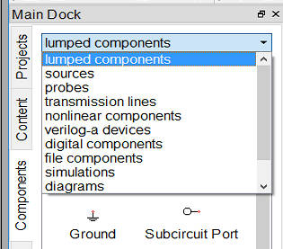
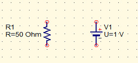
Place a resistor on the surface. You will find the resistor in the "lumped components" section of the drop down components menu:
When you have place the resistor use the selection tool to select it and then the rotation tool to turn it 90 degrees so that it is vertical. After this use the Set to Grid command to make is possible to wire it up later.
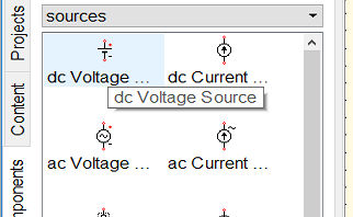
Next we need to put a battery symbol in the circuit. This will be found in the sources section. Generally in electronics we refer to anything that can generate a voltage or a current as a source. In this case we want a simple dc Voltage source otherwise often known as a battery.
 After placing the battery symbol into the schematic we are ready to wire up
: 
Use the wiring tool to connect the resistor to the battery/voltage source. This can be tricky at first but you quickly learn how to control what is happening. If you get it wrong the simplest thing to do is delete the wire, use the selection tool to select it and then press delete.
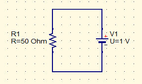
The final circuit is:
 One of the odd things about using Qucs is that you have to put a block that indicates the simulation type you want to carry out into the diagram. In this case we want to do a DC Simulation so select Simulations from the drop down menu and put a dc simulation block on the diagram
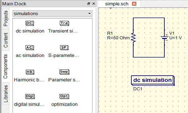
Now we can run a simulation. Use the command Simulation,Calculate DC bias or press F8. This works out the voltages at all points in the circuit and displays them on the schematic. Notice that you have to save the circuit before you can get the results.
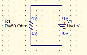
Of course this isn't particularly useful because we know that we are working with 1V battery and this voltage is placed across the resistor. However things get more complex and more useful very quickly.
What we would like to know is what the current in R1 is. There is a very easy way to find the current, voltage and any other quantity of interest but a very direct way to find the current is to insert a simulated current or ammeter.
You can find this in the probes section of the components drop down. You need to change the wiring to insert the current meter into the wire connecting the battery to the resistor. Notice that is is obvious that to measure a current the current has to flow through the measuring device so you have to wire it in as shown. In practice this makes measuring a current in a real circuit a very tedious operation because you usually have to break into a wire or worse a track on a PCB. Voltages are much easier to measure in practice because you don't need to break into wires - see the next chapter. Of course in a simulation placing a current device is a matter of a few clicks.
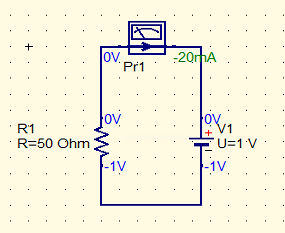
If you rerun the DC bias calculation you will see that the current is -20mA. Why minus? Simply because the current meter measures current flow relative to the arrow shown in is symbol. You can change the direction of the arrow by mirroring the symbol about the Y axis.
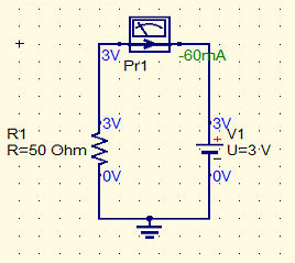
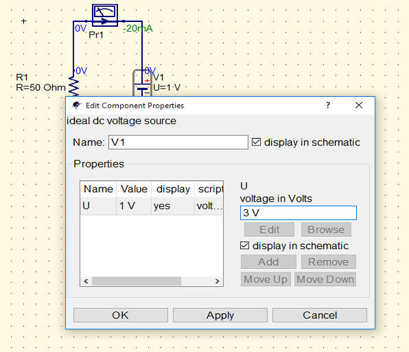
To make this simulation do some useful work we can now change the battery voltage to 3V to check the calculation in the first chapter. Right click on the battery and change the voltage in the dialog box that appears:
With the voltage set to 3V you can now repeat the simulation - press F8 to see:
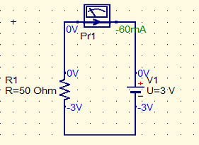
This agrees with the calculation in chapter 1 but which leaves us one last problem.
Why are the voltages shown as -3V rather than +3V?
The answer is that you have to specify where the 0V point is in the circuit by placing an earth or ground symbol. Where ever you place ground is at zero volts and the other voltages are calculated relative to this. Where you take the zero when measuring voltages is more-or-les arbitrary.
With a ground symbol, you can find it in the toolbar, the voltages in the simulation work out correctly: