Drive Characteristics
The characteristics of the Pi's I/O lines are quite complicated and best tackled in stages.
All of the GPIO lines can either be used as general purpose GPIO lines or a dedicated alternative purpose such as implementing a UART - serial interface etc.
In this and closely following chapters the subject is the general purpose GPIO lines. Later chapters deal with alternate uses.
What we are concerned with in this chapter is just the basic configuration of a GPIO line.
The key features is that as an input the GPIO line is high impedance - you can effectively ignore it when you connect to another circuit.
In output mode a single GPIO line can source and sink 16mA.
Unfortunately the Pi power supply can only supply enough power for all of the GPIO lines working at 3mA each. If you use too much current drive then the 3.3V supply will fail. For a Pi 1 the limit is around 50mA in total and for a Pi 2 and later then you can draw 100mA. However when you get close to these limits you might find that current spikes cause strange behavior.
In practice if you are planing to use more than 3mA from multiple GPIO lines consider using a transistor. If your circuits draw more than 50 or 100mA from the 3.3V supply rail consider a separate power supply. You can use the 5V supply with a regulator if you need more 3.3V current.
Notice that there is a subtle distinction here between current supplied by a GPIO line - which should always be less than 16mA and the current taken from the 3.3V power supply which should be less than 100mA.
The situation is complicated because the amount of power the Pi takes from the 3.3V supply depends on what peripherals it is using.
Notice that the 16mA limit means that you cannot safely drive a standard 20mA red LED without restricting the current to below 16mA. A better solution is to use a low power 2mA LED.
Finally it is worth mentioning that the GPIO line can be configured to use push-pull, pull up or pull down drive. In addition you can set the strength of the drive. More of this later.
Output
The bcm2835 functions that you need to make use of a pin in output mode are very simple.
The basic configuration function is:
void bcm2835_gpio_fsel (uint8_t pin, uint8_t mode)
This will set a pin specified by GPIO number to a given mode. The two most commonly use modes are:
BCM2835_GPIO_FSEL_INPTBCM2835_GPIO_FSEL_OUTP
These set the GPIO line to either input or output.
So to set the GPIO line connected to pin 7 on a Pi B+ or later you would use:
bcm2835_gpio_fsel(RPI_BPLUS_GPIO_J8_07, BCM2835_GPIO_FSEL_OUTP);
Once you have set the line to output there are a range of ways to set its state to high or low voltage output. The number of possibilities is initially confusing but they each have their particular use.
The simplest and most often used is:
void bcm2835_gpio_write (uint8_t pin, uint8_t on)
As always you specify the GPIO number or use one of the Physical pin enumeration values. The on parameter can be either
HIGH
or
LOW
So to set the GPIO line on pin 7 to high you would use:
bcm2835_gpio_write(RPI_BPLUS_GPIO_J8_07, HIGH);
and to set it low:
bcm2835_gpio_write(RPI_BPLUS_GPIO_J8_07, LOW);
As HIGH is defined to be 1 and LOW 0 you can also write
bcm2835_gpio_write(RPI_BPLUS_GPIO_J8_07, 1);
and use a variable is you want to:
  int state=1;
  bcm2835_gpio_write(RPI_BPLUS_GPIO_J8_07, state);
Write is useful when you want to call a single function and set the state of the line. However there are times when you always want to set a line high or low. In this case you can use one of:
void bcm2835_gpio_set (uint8_t pin)void bcm2835_gpio_clr (uint8_t pin)
As you can guess set sets the line to high and clr sets the line low. For example to set pin 7 high:
void bcm2835_gpio_set (RPI_BPLUS_GPIO_J8_07);
Multi Functions
So far the functions have allowed us to change one line at at time. If you want to change more than one line then there are "multi" equivalents of the write, set and clr functions:
void bcm2835_gpio_write_multi (uint32_t mask, uint8_t on)
void bcm2835_gpio_set_multi (uint32_t mask)
void bcm2835_gpio_clr_multi (uint32_t mask)
In this case you have to supply a "mask" to indicate which GPIO lines are to be altered. The mask is very simple each of the 32 bits in the mask represent a GPIO line - bit zero is for GPIO 0, bit one is for GPIO 1 and so on. Of course the problem here is that you can select GPIO lines that aren't brought out on the Pi's connector and which GPIO corresponds to which pin? Fortunately it is very easy to automatically make up a mask that corresponds to any set of GPIO lines specified by pin number. Suppose you want a mask for pin 3 then this means you need to set the third bit in the mask. This can be done using 1<<3 i.e. 1 shifted three places to the left - i.e. this is the mask you require and it it a general algorithm.
If you want a masks for pin n all you have to do is
1<<n
Now suppose you want a mask for pin n and pin m. All you have to do is or the masks for each pin together so the complete mask is:
(1<<n) | (1<m)
Of course you can use the pin enumeration in place of pin numbers so to create a mask for pin 3 and pin 5 you would use:
uint32_t mask=(1 << RPI_GPIO_P1_03) | (1 << RPI_GPIO_P1_05);
Once you have the mask you can use it in any of the multi functions. For example:
bcm2835_gpio_set_multi (mask);
sets both pin 3 and pin 5 to high in one operation.
There is another mask function which can be used to set multiple GPIO lines to different values:
void bcm2835_gpio_write_mask (uint32_t value, uint32_t mask)
In this case the mask parameter works in the same way and specifies which GPIO lines are to be involved. The difference is that the value parameter determines what each of the lines is to be set to. So for example if bit 6 of the mask is a 1 then GPIO line 6 will be set to whatever bit 6 of the value parameter is. This allows you to set multiple GPIO lines to different states. For example
uint32_t mask=(1 << RPI_GPIO_P1_03) | (1 << RPI_GPIO_P1_05);
uint32_t value=1<< RPI_GPIO_P1_05);
bcm2835_gpio_write_mask (value, mask);
Will set pin 3 to low and pin 5 to high because the mask specifies these pins and in value the bit corresponding to pin 3 is low and the bit corresponding to pin 5 is high. Notice the state of bits in value that do not correspond to bits set to 1 in mask have no effect.
The mask function are very useful when you want coordinated changes across a number of GPIO lines.
Drive Characteristics
The GPIO output can be configured into one of a number of modes but the most important is pull-up/down.
Before we get to the code to do the job it is worth spending a moment explaining the three basic output modes.
In pushpull mode two transistors of opposite polarity are used, for example:
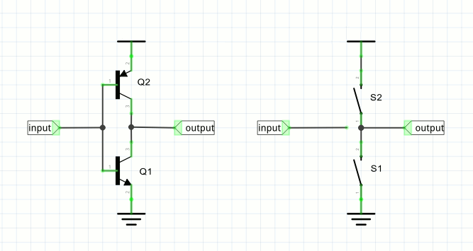
The circuit behaves like the two-switch equivalent shown on the right. Only one of the transistors, or switches is "closed" at any time. If the input is high then Q1 is saturated and the output is connected to ground - exactly as if S1 was closed. If the input is low then Q2 is saturated and it is as if S2 was closed and the output is connected to 1.8V.
You can see that this pushes the output line high with the same "force" as it pulls it low.
This is the standard configuration for a GPIO output.
The pullup mode replaces one of the transistors by a resistor:
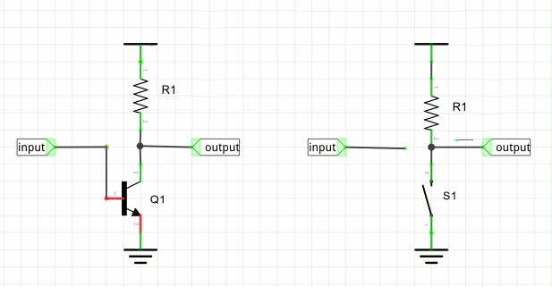
In this case the circuit is equivalent to having a single switch. When the switch is closed the output line is connected to ground and hence driven low. When the switch is open the output line is pulled high by the resistor.
You can see that in this case the degree of pulldown is greater than the pullup, where the current is limited by the resistor. The advantage of this mode is that it can be used in an AND configuration. If multiple gpio or other lines are connected to the output, then any one of them being low will pull the output line low. Only when all of them are off does the resistor succeed in pulling the line high.
This is used, for example, in a serial bus configuration like the I2C bus.
Finally the pulldown mode is exactly the same as the pullup only now the resistor is used to pull the output line low:
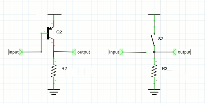
In the case of the pulldown mode the line is held high by the transistor but pulled low by the resistor only when all the switches are open. Putting this the other way round - the line is high if any one switch is closed.
Generally speaking the pushpull mode is best for driving general loads, motors, LEDs, etc.
The pullup/down modes are used where you need to create a serial bus of some sort or when the load needs this sort of drive.
To set the mode for a GPIO line the simplest function to use is:
bcm2835_gpio_set_pud (uint8_t pin, uint8_t pud)
where the pin is specified in the usual way and pud can be any of:
BCM2835_GPIO_PUD_OFF
BCM2835_GPIO_PUD_DOWN
BCM2835_GPIO_PUD_UP
Off is the default and you have to explicitly set down and up if required.
The internal pullup/down resistors are in the range 50K to 65K Ohms. There are also external 1.8K Ohm pull ups on pins 3 and 5. The only way to remove these pull ups is to unsolder the resistors from the board.