Controlling An LED
You can use a PWM supply to control the brightness of an LED for example, or the rotation rate of a DC motor. The only differences in applications such as these are to do with the voltage and current you need to control and the way duty cycle relates to what ever the physical effect is. In other words if you want to change some device by 50% how much do you need to change the duty cycle?
For example how do we "dim an LED"?
By changing the duty cycle of the PWM pulse train you can set the amount of power delivered to an LED, or any other device, and hence change its brightness.
For example for an LED we might use a 3.3V supply and a current of a few tens of milliamps. In the case of an LED the connection between duty cycle and brightness is a complicated matter but the simplest approach uses the fact that the perceived brightness is roughly proportional to the cube of the input power. The exact relationship is more complicated but this is good enough for most applications. As the power supplied to the LED is proportional to the duty cycle we have:
b=kd3
where b is the perceived brightness and d is the duty cycle.
Notice that as the LED when powered by a PWM signal is either full on or full off there is no effect of the change in LED light output with current - the LED is always run at the same current.
What all of this means is that if you want an LED to fade in a linear fashion you need to change the duty cycle in a non-linear fashion. Intuitively it means that changes when the duty cycle is small produce bigger changes in brightness than when the duty cycle is large.
For a simple example we need to connect a standard LED to the PWM line.
Given that all of the Pi'sGPIO lines work at 3.3V and ideally only supply a few milliamps we need a transistor to drive the LED which typically draws 20mA.
You could use an FET of some sort but for this sort of application an old fashioned Bipolar Junction Transistor works very well and is cheap and available in a through hole mount - i.e. it comes with wires.
Almost any general purpose npn transistor will work but the 2N2222 is very common:
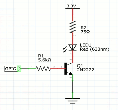
R1 restricts the current to 0.48mA which is very low and assuming that the transistor has a minimum hfe of 50 this provides 24mA to power it. R2 limits the current to 20mA. Notice that all of these values are for a red LED with forward voltage drop of 1.8V and typical current 20mA. LEDs of different color have different forward voltage drops and currents.
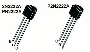
If you are using the 2N2222 then the pin outs are:
And of course, as always the positive terminal on the LED is the long pin.
Assuming that you have this circuit constructed then a simple PWM program to modify its brightness from low to high and back to low in a loop is;
   if (!bcm2835_init())
        return 1;
    bcm2835_gpio_fsel(18, BCM2835_GPIO_FSEL_ALT5);
    bcm2835_pwm_set_clock(2);
    bcm2835_pwm_set_mode(0, 1, 1);
    bcm2835_pwm_set_range(0, 1024);
    int w = 1;
    int inc = 1;
    for (;;) {
        bcm2835_pwm_set_data(0, w);
        w = w + inc;
        if (w > 1024 || w <= 0)inc = -inc;
        bcm2835_delayMicroseconds(5000);
    }
The basic idea is to set up a pulse train with a period of 1ms. Next in the for loop the duty cycle is set to 0% to 100% and then back down to 0%.
If you watch the flashing you will see that it changes brightness very quickly and then seems to spend a long time "stuck" at almost full brightness and then suddenly starts to dim rapidly. This is a consequence of the way the human eye perceives light output as a function of input power.
Changing the LED brightness
What about a linear change in brightness?
To achieve this reasonably accurately isn't difficult all we need to do is increase the power or equivalently the duty cycle in steps that are cubic. If we just use 0 to 10 cubed we get a pulse width of 0 to 1000 which is ideal for our 1024 pulse range used in the previous example i.e. 0 to close to 100% duty cycle.
If you need the ultimate speed you could precompute the powers but for simplicity we will just use integer multiplication:
  int w = 0;
    int inc = 1;
    for (;;) {
        bcm2835_pwm_set_data(0, w*w*w);
        w = w + inc;
        if (w > 10 || w <= 0)inc = -inc;
        bcm2835_delayMicroseconds(50000);
    }
As this produces 10 cubic steps a wait_us of 50000 makes each step last 5ms and so it takes 50ms to go from low to high.
If you try the program you should find that you see the LED increase steadily towards a maximum and then decrease steadily to a minimum.
If you replace the delay with a value of 100,000 then you will get a 1 second cycle - which using only ten steps starts to look a little flashy in a not too good sense.
You can increase the number of steps by simply dividing by a suitable factor. If you cube 1 to 20 you get 1 to 8000 and dividing by 8 gives 0 to 1000. Dividing by 8 is just a matter of three right shifts and so while not very accurate does allow fast computation with integer arithmetic:
     int w = 0;
    int inc = 1;
    for (;;) {
        bcm2835_pwm_set_data(0, (w*w*w)>>3);
        w = w + inc;
        if (w > 20 || w <= 0)inc = -inc;
        bcm2835_delayMicroseconds(50000);
    }
Notice that now as there are twice as many steps we only need each one to last half the time, i.e. 50,000 microseconds.
You can also set the PWM to mode 0 i.e. balanced mode
bcm2835_pwm_set_mode(0, 0, 1);
This does make the LED look even smoother but the increase in RF noise makes it essential to put the Pi in a metal case.
In most cases exactly how linear the response of the LED is is irrelevant - a rough approximation looks as smooth to the human eye. The only exception is when you are trying to drive LEDs to create a grey level or color display when color calibration is another level of accuracy.